Need help for a super simple Cheapest USB POWER OUTAGE ALARM sketch

Thread Starter

dankori

Joined Jul 1, 2022
9
@dankori:
We are simple electronic professionals, and unfortunately,
we do not understand slang of utube guys (their "sketchs").
Please, provide us circuits diagrams, completed in
accordance with electrical schematic drawing standards.
For example, see https://www.allaboutcircuits.com/technical-articles/understanding-schematics/
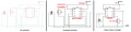
001.jpg002.jpg003.jpgI hope these are better.
My question is: Can I achieve my goal (of a circuit that whenever the usb power is down for about 10 seconds - the buzzer wakes up for about 10 seconds) with these simple components (which now I can simulate) ?
 
Last edited:

Thread Starter

dankori

Joined Jul 1, 2022
9
@dankori:
We are simple electronic professionals, and unfortunately,
we do not understand slang of utube guys (their "sketchs").
Please, provide us circuits diagrams, completed in
accordance with electrical schematic drawing standards.
For example, see https://www.allaboutcircuits.com/technical-articles/understanding-schematics/

I am new to electronics and my jargon is as far as my "you tube based" knowledge takes me.

also .. Electronics and " electrical schematic drawing standards " will be my third language to learn- and Sorry for any mistakes. English is not my native language ..
 

Danko

Joined Nov 22, 2017
2,223
@dankori:
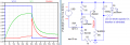
Your first circuit, redrawn, simulated.
Why you do not simulate your circuits in Tinkercad? https://maker.pro/custom/tutorial/how-to-design-and-simulate-circuits-in-tinkercad
If you do not like, how circuit works, change it and simulate again... and again... and again, if needed, while circuit will not works well.

1657013437781.png
ADDED:
About Youtube:
After youtube lessons human brains are damaged and it is almost impossible to repair them.
About simulator:
It will be better for you to design your circuits in free simulator LTspice:
https://www.analog.com/en/design-center/design-tools-and-calculators/ltspice-simulator.html
 
Last edited:

MisterBill2

Joined Jan 23, 2018
28,051
Here is a power fail alarm circuit from the mid 1950's, updated to use modern hardware and to run on 5 volts DC instead of the mains power direct. The warning device is a 5 volt electronic piezo sounder, the power supply is a 2 farad super-capacitor, and the logic element is a low-power spdt (single pole with both a normally open and a normally closed contact) relay. Other components are a cheap power diode, possibly 1N4001 or equal, and a 100 ohm resistor.
The circuit starts with the plus 5 volts from the source. That voltage connects to the 100 ohm resistor and then the diode, and then the other end of the diode connects to the coil of the relay.The other end of the relay coil connects to the negative side of the 5 volt source. So far, when the 5 volts are present the relay operates. That same junction of the resistor and diode also connects to the normally open contact of the relay so that when the relay is operated the 5 volts is fed to the relay contact common terminal, which is connected to the positive terminal of the 2 farad super capacitor. The negative terminal of the super capacitor is connected to the source negative at the other end of the relay coil.
Thus far, when the 5 volt source is active, and the 5 volts present, the capacitor is charging because the relay is operated. The positive connection of the 5 volt electronic piezo sounder is connected to the normally closed relay contact, which is held open when the relay is operated. The negative connection of the 5 volt electronic piezo sounder is connected to the negative terminal of the super capacitor and the source atthe "other end" of the relay coil.
The operation is like this: with the 5 volt supply active, the relay is energised and the NO contact is closed and so the super capacitor charges after w few minutes, because the 100 ohm resistor limits the charging current. After the capacitor is finally charged, if the 5 volt supply stops, the relay releases and the super capacitor is connected to the 5 volt electronic piezo sounder, and the power failure alarm is active. This warning starts immediately, unless an added electrolytic capacitor is connected across the relay coil, with the capacitor positive tied to the diode end of the coil. The required value of the capacitor will probably be near 1000 mfd.
There you have the simplest circuit with no jargon and no arduinos or sketches or other "nuts and Volts" secret words instead of normal ones.
 

Thread Starter

dankori

Joined Jul 1, 2022
9
Here is a power fail alarm circuit from the mid 1950's, updated to use modern hardware and to run on 5 volts DC instead of the mains power direct. The warning device is a 5 volt electronic piezo sounder, the power supply is a 2 farad super-capacitor, and the logic element is a low-power spdt (single pole with both a normally open and a normally closed contact) relay. Other components are a cheap power diode, possibly 1N4001 or equal, and a 100 ohm resistor.
The circuit starts with the plus 5 volts from the source. That voltage connects to the 100 ohm resistor and then the diode, and then the other end of the diode connects to the coil of the relay.The other end of the relay coil connects to the negative side of the 5 volt source. So far, when the 5 volts are present the relay operates. That same junction of the resistor and diode also connects to the normally open contact of the relay so that when the relay is operated the 5 volts is fed to the relay contact common terminal, which is connected to the positive terminal of the 2 farad super capacitor. The negative terminal of the super capacitor is connected to the source negative at the other end of the relay coil.
Thus far, when the 5 volt source is active, and the 5 volts present, the capacitor is charging because the relay is operated. The positive connection of the 5 volt electronic piezo sounder is connected to the normally closed relay contact, which is held open when the relay is operated. The negative connection of the 5 volt electronic piezo sounder is connected to the negative terminal of the super capacitor and the source atthe "other end" of the relay coil.
The operation is like this: with the 5 volt supply active, the relay is energised and the NO contact is closed and so the super capacitor charges after w few minutes, because the 100 ohm resistor limits the charging current. After the capacitor is finally charged, if the 5 volt supply stops, the relay releases and the super capacitor is connected to the 5 volt electronic piezo sounder, and the power failure alarm is active. This warning starts immediately, unless an added electrolytic capacitor is connected across the relay coil, with the capacitor positive tied to the diode end of the coil. The required value of the capacitor will probably be near 1000 mfd.
There you have the simplest circuit with no jargon and no arduinos or sketches or other "nuts and Volts" secret words instead of normal ones.
Thank you . I will test it asap.
 

MrAl

Joined Jun 17, 2014
13,769
Thank you all for the huge help and time spent on this.

While I wait for the components (mainly CD4049) to arrive I found an online simple simulation site called tinkercad and managed to tinker with all the different approaches I found online -to get me to my original goal.

While this may be too "noob"'s perspective on the solutions - they are still a good (start of a) solution for me.
I still have problems with each of them and decided to ask you guys( and girls??) on your perspective on each of the three approaches. I think The Relay approach is the simplest one.. View attachment 270746View attachment 270747View attachment 270748
Hi,

Can you post an actual schematic? That makes it a lot easier to examine for many of us.
 

MrAl

Joined Jun 17, 2014
13,769
I fixed some of your schematic:
After looking at the last drawing i can say that i dont think i would want to drive the speaker in such a manner.
First, the impedance is only 33 Ohms apparently which may be too big of a load for the IC chip.
Second, the speaker will have a net DC which will mean the speaker will always be pushed out or pulled in slightly. Most apps that drive speakers like that use a coupling capacitor and this one probably a low value resistor too maybe 100 Ohms or something, and watch out for reverse kickback into the IC chip from a voltage that goes too negative or even too positive (remember this can be a boost circuit too with the output across the speaker and output of the IC chip ha ha) so might need clamping diodes.
 

MisterBill2

Joined Jan 23, 2018
28,051
After looking at the last drawing i can say that i dont think i would want to drive the speaker in such a manner.
First, the impedance is only 33 Ohms apparently which may be too big of a load for the IC chip.
Second, the speaker will have a net DC which will mean the speaker will always be pushed out or pulled in slightly. Most apps that drive speakers like that use a coupling capacitor and this one probably a low value resistor too maybe 100 Ohms or something, and watch out for reverse kickback into the IC chip from a voltage that goes too negative or even too positive (remember this can be a boost circuit too with the output across the speaker and output of the IC chip ha ha) so might need clamping diodes.
That item may not be a speaker, the 33 ohmspeaker is also on a different thread. My design uses a two terminal piezo sounder, a much more piercing sound and draws less current.
 

MisterBill2

Joined Jan 23, 2018
28,051
Five or six components and no backup battery and no close tolerance components, No need for well filtered power, either. Only one semiconductor, and that is a diode.
The original version used a M500 rectifier and a 200 volt electrolytic capacitor, a neon bulb for an oscillator, a PM speaker and transformer, and could be added to an AC/DC five tube radio using the radio's rectifier and speaker/output transformer as well.
The new version is smaller and uses much less power, and probably is a bit louder as well.
 

Ya’akov

Joined Jan 27, 2019
10,278
ADDED:
About Youtube:
After youtube lessons human brains are damaged and it is almost impossible to repair them.
About simulator:
It will be better for you to design your circuits in free simulator LTspice:
https://www.analog.com/en/design-center/design-tools-and-calculators/ltspice-simulator.html
Hey, Danko. You are really painting YouTube with two broad a brush. There are many excellent resource for electronics education and application available. Just off the top of my head (they employ varying styles, not all of these channels will please any one person, but they all offer very good quality material).

Great Scott General practical electronics with explanations of components and circuits
Electroboom Entertaining discussions about theory and practice from a working engineer
Andreas Spiess MCUs and IoT with a focus on wireless and low power operation (with a Swiss accent)
AfroTechMods Basic component information, practical circuits, test gear reviews
Big Clive Cheap eBay device teardowns with schematics and explanations of operation, lots more!
Ralph S. Bacon Arduino focused tutorials, along the way circuits, components, and PCB fab in a step-by-step format
Mr. Carlson‘s Lab Equipment repair, practical devices, etc, with a focus on vintage and test gear
Adafruit Labs The official Adafruit channel with tutorials, product applications, and new product news
Sparkfun The official Sparkfun channel with tutorials, product applications, and new product news
Element 14 Presents The official Element 14 channel with tutorials, product applications, and new product news
The Engineering Mindset Clear explanations of key devices form auto alternators to batteries, to purely mechanical devices
Khan Academy An extensive educational channel covering math, physics, and electrical topics among many others
Walter Lewin The MIT lectures of Professor Walter Lewin with coverage of e-mag with great depth and accessibility
Electrician U Dustin Stelzer, master electrician (in the US) explains professional residential and commercial eletrical topics
Artisan Electrics UK-based electrician showing practical electrics in the UK entertainingly with actual examples

These are just a few that I could easily recall. The list of good content channels related to electronics, electrical engineering, and other topics discussed on AAC is at least 10 times this, quite possibly an order of magnitude higher.

This is not to say there isn’t garbage and misinformation on YouTube, and it does probably outnumber the channels with good content, but it’s a baby and bath water problem. Writing off a really excellent resource for both the beginner and expert alike because it can also be bad just isn’t right.
 

MisterBill2

Joined Jan 23, 2018
28,051
Certainly there may be "good channels" on youtoob, but there is a whole lot of faked garbage and incorrect stuff as well. Sixteen OK locations that appear to be OK and how many hundred that are not.
So IT IS an area with hazards.
 

Danko

Joined Nov 22, 2017
2,223
Hey, Danko. You are really painting YouTube with two broad a brush.
Yes, it is precaution, because YouTube territory is dangerous for TS.
There are many excellent resource for electronics education and application available. Just off the top of my head (they employ varying styles, not all of these channels will please any one person, but they all offer very good quality material).
======list of channels======
You was able to select these channels because you already took education in electronics.
TS can not.

YouTube really is university for TS.
What can you say about university, where in books, only some pages contain right information,
rest of them carry disinformation?
Where only some professors are adequate educated, but most of them are cheaters and ignorant persons?
Where good lectures, as always, are academically boring, but fake lectures are very spectacular?

And more: video presentations eliminate ability of abstract thinking and replace it by set of templates.
 

Ya’akov

Joined Jan 27, 2019
10,278
Yes, it is precaution, because YouTube territory is dangerous for TS.

You was able to select these channels because you already took education in electronics.
TS can not.

YouTube really is university for TS.
What can you say about university, where in books, only some pages contain right information,
rest of them carry disinformation?
Where only some professors are adequate educated, but most of them are cheaters and ignorant persons?
Where good lectures, as always, are academically boring, but fake lectures are very spectacular?

And more: video presentations eliminate ability of abstract thinking and replace it by set of templates.
It‘s true that the bad of YouTube ranges from bad to truly terrible, and that some of the channels that purport to teach electronics are simply commercial scams almost the same as the “free energy” channels that look very much like them, except they actually build “working“ things. However those working things are often poorly designed, or workarounds to use fewer, cheaper parts, or dangerous, etc.

But, YouTube is also a potentially wonderful resource fo the autodidact. If a person is satisfied with dead bug construction to make some trivial device not concerned with its safety or efficiency then recommendations of better channels isn’t likely to influence them since it requires a lot more work to do things right.

But, if they are interested in learning the principles and practices of electrical engineering, even as a hobbyist, suggesting that YouTube is an unmitigated wasteland is quite damaging. Most people today would rather watch a video than read a book. If bad videos are what got them to the point of wanting to really understand, in my view suggesting good videos is the right course.

Yes, I know more than they do about what is good and bad on YouTube, but that’s what a mentor is about—communicating wisdom born of study and experience. So, warning people against the bad and suggesting the good seems to me that much better course than the wholesale dismissal of what i know to be a really very good resource because, like the world it arises from, there is more bad than good in that “place”.
 

MisterBill2

Joined Jan 23, 2018
28,051
I recommend textbooks as learning tools for technical stuff. I realize that this is an ancient point of view, but a really good value can be found in used college texts at a used book store. Freshman physics books can provide explanations about electrons and current and even magnetism, along with the math to describe the relationships. And the benefit is that one can go over a section many times without having to hit the replay icon.
An introductory electrical text will explain circuits and resistance and current versus voltage drops,and the book from 1955 is just as good as a recent text for the basic theory, which has not changed. The discussions about AC circuits, reactance and phase angles are all still applicable and correct. Only silicon diodes are missing.
 

MrAl

Joined Jun 17, 2014
13,769
Hey, Danko. You are really painting YouTube with two broad a brush. There are many excellent resource for electronics education and application available. Just off the top of my head (they employ varying styles, not all of these channels will please any one person, but they all offer very good quality material).

Great Scott General practical electronics with explanations of components and circuits
Electroboom Entertaining discussions about theory and practice from a working engineer
Andreas Spiess MCUs and IoT with a focus on wireless and low power operation (with a Swiss accent)
AfroTechMods Basic component information, practical circuits, test gear reviews
Big Clive Cheap eBay device teardowns with schematics and explanations of operation, lots more!
Ralph S. Bacon Arduino focused tutorials, along the way circuits, components, and PCB fab in a step-by-step format
Mr. Carlson‘s Lab Equipment repair, practical devices, etc, with a focus on vintage and test gear
Adafruit Labs The official Adafruit channel with tutorials, product applications, and new product news
Sparkfun The official Sparkfun channel with tutorials, product applications, and new product news
Element 14 Presents The official Element 14 channel with tutorials, product applications, and new product news
The Engineering Mindset Clear explanations of key devices form auto alternators to batteries, to purely mechanical devices
Khan Academy An extensive educational channel covering math, physics, and electrical topics among many others
Walter Lewin The MIT lectures of Professor Walter Lewin with coverage of e-mag with great depth and accessibility
Electrician U Dustin Stelzer, master electrician (in the US) explains professional residential and commercial eletrical topics
Artisan Electrics UK-based electrician showing practical electrics in the UK entertainingly with actual examples

These are just a few that I could easily recall. The list of good content channels related to electronics, electrical engineering, and other topics discussed on AAC is at least 10 times this, quite possibly an order of magnitude higher.

This is not to say there isn’t garbage and misinformation on YouTube, and it does probably outnumber the channels with good content, but it’s a baby and bath water problem. Writing off a really excellent resource for both the beginner and expert alike because it can also be bad just isn’t right.
Hi,

That's a good list i think.
Yeah a lot of good stuff, and in my searches i only found a handful of stupid faked or just wrong stuff. Even in the best company there are mistakes and missing information but that's life. Even in books there are mistakes some of the best electrical books i have read have mistakes with wrong answers to problem questions. It's just part of life.

Some examples of the stupid stuff:
** An article on a full analysis of a rectifier circuit but with no capacitor ESR. The main point of the article was to show the equation(s) for the analysis, yet the equations had typos. Ruined the whole article, although it was possible with some time spent to figure out what was wrong. Not too bad.
** Another article on an electronic circuit. Missing half of the equation. Had to go through the entire analysis from scratch to reproduce the equation.
** The worst i have found was a guy who faked programming a remote control to control an air conditioner. He stated and "illustrated via video" that you can program any remote by having the air conditioner send codes to the remote control. The entire thing was faked, including the video that "proved" that it worked. I think people like this should be banned from YouTube at least for a while. This is the worst of them all with big intent to deceive.

I guess all in all i have found most things on the net to be worthy of reading, but there does seem to be a correlation between the level of technicality and correctness. The more advanced and detailed the topic, the more tendency to be incorrect through typos or just necessary info that is missing.
I have also found, unfortunately, that a lot of the really advanced stuff is hidden behind a paywall. That's very frustrating sometimes.
 

MrAl

Joined Jun 17, 2014
13,769
That item may not be a speaker, the 33 ohmspeaker is also on a different thread. My design uses a two terminal piezo sounder, a much more piercing sound and draws less current.
I would think a piezo would be ok as long as it does not draw too much current. I guess a measurement is a good idea and check for voltage transients.
 

Tonyr1084

Joined Sep 24, 2015
9,744
Okay, I missed that you wanted the buzzer to stop 10 seconds after the 10 second delay.
Revised schematic below:

Since the buzzer now shuts off automatically, you don't need a switch.

View attachment 270537
BUT! How long before the 9V battery is drained? I did something similar for a freezer door alarm and discovered that for some reason beyond my skill or understanding level lasted for only two weeks. My concern is for the longevity of the battery - and no - please don't make a separate thread for my question. I'M NOT ASKING - I'M POINTING OUT! Some moderators have taken my questioning as hijacking. I'm only pointing out that using a 9V battery with a 1megΩ resistor will still drain. And at some point it's going to be too weak to react with an alarm.

The super-cap seems like a good idea, but as you pointed out - expense may be an issue. Another issue would be audibility of the buzzer (I didn't see one defined by the TS, maybe I missed that). What kind of power is it going to draw?
 
Top