It's for a replacement, but I added the final thought about repairs to the dimmer switch just in case someone experienced with these might have another option that will get my problem solved sooner than waiting for the replacement part.
I just realised that my post failed to add my qoute/questions that I included with the pics....I need a potentiometer that can handle the load of a black and decker 12v 250ma 4watt power supply. This is powering approx 30 feet rgb led strip lights that are framing 2 large wall mirrors in the corner of my bedroom. I want to keep them dimly lit at night but need to reduce the 12v down to 4v or less. A 5v usb phone charger is just a little to bright even with the 44 key remote control that runs the lights. My final thought on the repair is in the picture i posted you can see that whoever assembled the dimmer switch did not double check their work and soldered the 2 +input/output posts together. I have fixed that but still the only way I get full power from the dimmer switch is half way up and thats shorting out some how and will not let me change the light colors. It illuminated all of them. Hopefully this posts properly and I don't have to type this a 3rd time...saving to my clipboard incase.... thanks in advance and hopefully I included enough information.
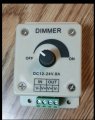
Is the potentiometer to be used instead of the PWM controller in your pictures or is it to replace a faulty potentiometer in you existing PWM controller ? Also 12 volts at 250 mA is only 3 watts (Not 4) I was about to comment about the solder splash between the two middle pins at the bottom of the board but I decided to check on the TO220 device on the board. It is an N channel mosfet so the load would probably be between the positive rail and the drain of the mosfet. If I am right then the positive input and positive output would be connected together. (The two middle pins in the picture.) The negative input would NOT be connected to the negative output. I think you will find that even though you have removed the solder splash they will still be connected together.
Pot ratings are a little different than many other component ratings like fixed resistors because when the shaft is turned it could mean that the whole pot is no longer being used but only part of it physically. When a fixed resistor is used, the entire physical body and whatever is inside is being used all the time, so there's no question usually about the power rating. But when we turn the pot one way, we start to use less and less of the part that makes up the resistance and since power dissipation is related to the physical dimensions, we have to pay close attention to what is happening inside.
As an extreme example, suppose we have a 100 Ohm linear slide pot that is rated for 1 watt. That means that ideally the max voltage across the two ends of the pot (arm open) is 10 volts because power is P=10^2/100=1 watt. The resistance strip inside might be 2 inches long so we have 1 watt being dissipated across that 2 inch full section.
Now suppose we apply that 10 volts across one arm and one end and turn the pot to get full resistance. We still have 10 volts across 100 ohms whcih is still 1 watt. But what happens when we start to turn the pot to decrease the resistance. IF we turn it down to 90 ohms with that same 10 volts we have power 1.11 watts which is over the rating now.
What else is interesting is that the actual power is distributed over only 9/10 the area as it was before, so we should have derated the power first and that would bring it down to a rating of 0.9 watts, so really now we are applying 1.11 watts to a part rated for only 0.9 watts.
You can see how this goes. As we turn the pot shaft, we have to be aware of this power derating mechanism.
A common application where this comes into play is in a simple LM317 regulator circuit where we try to get the full 30v output (or something around that level). If we use a pot with a rating too low it burns out.
im using the white ones you see pictured for the mirrors..3528 rgb 300 led strip light but also have the black ones that have all 3 colored leds built into one module and plan on switching over to these. heres the ebay link if anyone is interested in purchasing them for 8.00 https://www.ebay.com/itm/5M-20-Colo...e=STRK:MEBIDX:IT&_trksid=p2057872.m2749.l2649
Is the potentiometer to be used instead of the PWM controller in your pictures or is it to replace a faulty potentiometer in you existing PWM controller ? Also 12 volts at 250 mA is only 3 watts (Not 4) I was about to comment about the solder splash between the two middle pins at the bottom of the board but I decided to check on the TO220 device on the board. It is an N channel mosfet so the load would probably be between the positive rail and the drain of the mosfet. If I am right then the positive input and positive output would be connected together. (The two middle pins in the picture.) The negative input would NOT be connected to the negative output. I think you will find that even though you have removed the solder splash they will still be connected together.
sorry i posted incorrectly with the 250 mA it is actually 210 mA and has 4 watts on the label. i posted a picture of it in the previous response to be80be.the potentiometer is meant to replace both the board and the potentiometer as i do not know which one is faulty. in the picture i just posted you can see both the 5v usb and the 12v power supply that i temporarily connected to be able to dim them down at night until i get the dimmer switched resolved. at 5v only half the led are lit but i would like to be able to dim more and have more control of it. actually earlier i forgot to unplug the 12v power supply when i plugged in the usb and i fried my led controller and had to replace it with a second one i had. my thoughts on that is that i burnt one of the diodes at the beginning of the circuit. i will mess with diagnosing and fixing it after i get the potentometer issue resolved. dont want to get off topic.heres a couple pics showing them on 5v and on 12v and you can see it only powers half the leds thanks for the help
Pot ratings are a little different than many other component ratings like fixed resistors because when the shaft is turned it could mean that the whole pot is no longer being used but only part of it physically. When a fixed resistor is used, the entire physical body and whatever is inside is being used all the time, so there's no question usually about the power rating. But when we turn the pot one way, we start to use less and less of the part that makes up the resistance and since power dissipation is related to the physical dimensions, we have to pay close attention to what is happening inside.
As an extreme example, suppose we have a 100 Ohm linear slide pot that is rated for 1 watt. That means that ideally the max voltage across the two ends of the pot (arm open) is 10 volts because power is P=10^2/100=1 watt. The resistance strip inside might be 2 inches long so we have 1 watt being dissipated across that 2 inch full section.
Now suppose we apply that 10 volts across one arm and one end and turn the pot to get full resistance. We still have 10 volts across 100 ohms whcih is still 1 watt. But what happens when we start to turn the pot to decrease the resistance. IF we turn it down to 90 ohms with that same 10 volts we have power 1.11 watts which is over the rating now.
What else is interesting is that the actual power is distributed over only 9/10 the area as it was before, so we should have derated the power first and that would bring it down to a rating of 0.9 watts, so really now we are applying 1.11 watts to a part rated for only 0.9 watts.
You can see how this goes. As we turn the pot shaft, we have to be aware of this power derating mechanism.
A common application where this comes into play is in a simple LM317 regulator circuit where we try to get the full 30v output (or something around that level). If we use a pot with a rating too low it burns out.
Have you noticed thet the LED strips in your Ebay link require 2 amps at 12 volts. This is almost 10 times the rating of the power supply that you have. Also the controller with this set may already provide the dimming function. Even if it does not then reducing the supply voltage much below 12 volts will probably stop the electronics in the controller from working. You may be better off just buying the RGB LED strip and adding you own dimmer circuit.
Note the confusion over the 4 watt rating of your existing power supply is because the 4 watt rating is the input power. The output power will be 12 volts x 0.21 amps = 2.52 watts.
Ok thanks, and i will post a reply to your reply some time after that, and then you can post a new reply to my reply to your first reply and then someone else might post a reply to that, etc., etc.
But on the more serious side, what are those pic's all about? The LED display looks kind of cool but it's hard to tell what it is actually doing and how it is set up there. Also, what it is supposed to accomplish. Is this for a sales setup where the lights attract customers or something like that, or just for home use just to make things look interesting.
this is just for home to make the bedroom look nice and also using these mirrors for photogragphy with my t5 rebel camera. also wanting to use the led lights for a night light which is where the dimmer comes into play that this thread is regarding.pics
Have you noticed thet the LED strips in your Ebay link require 2 amps at 12 volts. This is almost 10 times the rating of the power supply that you have. Also the controller with this set may already provide the dimming function. Even if it does not then reducing the supply voltage much below 12 volts will probably stop the electronics in the controller from working. You may be better off just buying the RGB LED strip and adding you own dimmer circuit.
Note the confusion over the 4 watt rating of your existing power supply is because the 4 watt rating is the input power. The output power will be 12 volts x 0.21 amps = 2.52 watts.
yes the controller has a dimmer built in but does not make a huge difference. i have 4 of the 5v usb controllers also but they only light half the strips and i dont want to switch them out every night. also i have looked at another dimmer control but i do believe this would be used instead of my current controller and i would loose the remote and all the features that unit has. also i believe all this 3 knob/channel is is 3 poteniometers, one for each color led. https://www.ebay.com/itm/DC12-24V-3...e=STRK:MEBIDX:IT&_trksid=p2055119.m1438.l2649
Have you noticed thet the LED strips in your Ebay link require 2 amps at 12 volts. This is almost 10 times the rating of the power supply that you have. Also the controller with this set may already provide the dimming function. Even if it does not then reducing the supply voltage much below 12 volts will probably stop the electronics in the controller from working. You may be better off just buying the RGB LED strip and adding you own dimmer circuit.
Note the confusion over the 4 watt rating of your existing power supply is because the 4 watt rating is the input power. The output power will be 12 volts x 0.21 amps = 2.52 watts.
i have changed my power supply since i first made this post after digging through old electronics i found a power supply from an extra router that has 12v @ 1 amp and has a connecter to plug into the led controller w/o any mods. also found a cord with the proper end to connect to controller and then has usb on other end. this however still does not solve my problem and does not allow me to have controll over how much i dimm them
I My final thought on the repair is in the picture i posted you can see that whoever assembled the dimmer switch did not double check their work and soldered the 2 +input/output posts together.
Ok thanks, and i will post a reply to your reply some time after that, and then you can post a new reply to my reply to your first reply and then someone else might post a reply to that, etc., etc.
But on the more serious side, what are those pic's all about? The LED display looks kind of cool but it's hard to tell what it is actually doing and how it is set up there. Also, what it is supposed to accomplish. Is this for a sales setup where the lights attract customers or something like that, or just for home use just to make things look interesting.
oh and the pics were just to show how the lights illuminate on 5v half light, and the the other is them on 12v and then the one showing them on 12v with the overhead lights on to give a better pic of how they are being used
 Facebook
 Google
 GitHub
 Linkedin

 355.7 KB Views: 20


")


