need help building a scoreboard counter

elec_mech

Joined Nov 12, 2008
1,500
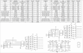
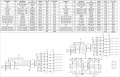
If we keep everything as I've shown in the schematic, you'll need at least 2.2A or 2200mA, so a 2500mA supply is good.

Let me clarify a few things then let's look at some alternatives you may want to explore. In the meantime, I strongly suggest not ordering anything until we work out all the kinks - the first few times you tackle an electronics project, there is an almost irresistible temptation to order parts as soon as possible. From first hand experience, don't do it. This will save you a lot of time in the long run as well as money since things can change instantly in the design stage.

Okay, a MOSFET shouldn't run more than a buck or two. Maybe a few bucks on the high side if we need something to handle a lot of current (which we don't), so adding one wouldn't be costly.

Reverse voltage protection applies to the power supply, in this case a DC supply. A DC supply that plugs into a wall will not be affected by how your house is wired. House wiring is AC which does not have a polarity. However, the output plug of DC supply will have a polarity and this is where we concern ourselves. If you study them closely, most supplies use a barrel plug with a tip and a sleeve. You can often get the same size plug in both polarities, i.e., tip positive and sleeve negative OR tip negative and sleeve positive. If someone plugs in a barrel with the wrong polarity, the circuit will be damaged if no protection is on the circuit. Another thing that could happen is the dog chews up the cord and someone decides to fix it but accidentally reverses the polarity.

I agree the bridge rectifier design is nice and allows the circuit to work regardless of polarity or AC or DC is supplied (so long as the voltage is correct).

Alright, your resistor calculations are good (though the webpage shows V_LED is 3.5V), but 0.238W is too close to 0.25W to be safe. Therefore, you'll want to use 0.5W resistors here. But, since you plan to use two digits (front and back), we can get a little clever here. You could wire the 1-inch displays in series, e.g., segment a of the front team A win is wired in series with segment a of the back team A win, which then gives us: 16.6V - 3.7 - 3.7 - 1 = 8.2V. Then R = 410 ohm (470 ohm could be used). This then gets our wattage under 0.18W - while still a little high, this should be okay for 0.25W resistors. You may still want to use 0.5W to be safe. In any case, you also reduce your resistor count to half for the 1-inch displays.

A bridge rectifier can be made with four regular diodes, but since we need over 2A, I suggest we just get a dedicated bridge rectifier. I won't cost much compared to rolling your own and it will be easier to wire since they all have markings on the input and output.

I'm slowly looking through the BOM you sent me for some prototyping supplies. I can help you save several bucks (to a point, depending on shipping from two supplies as opposed to one), but again, I'll need sometime. Take a look at Electronics Express for breadboards and jumper wires or even eBay. But I'll put something together to try to get as much at the best price from the fewest sources as reasonably possible - again, if you have the time to wait.
 

Thread Starter

eric71m

Joined Feb 18, 2015
15
I did some updating to the parts list today...
I will continue to modify it tomorrow with the resistors and breadboards.
Thanks for the advice to wait to order parts, I was henching towards pulling the trigger on the displays, but I know what you mean about ordering materials too soon... I've too have learned my lesson, only in the wood working side, and materials can be very expensive and also non returnable...
I'll pm you with my updated parts list.
 

elec_mech

Joined Nov 12, 2008
1,500
Okay, I've made some time to look over this in detail and have a basic bill of materials (BOM). I've tried to drawn and label everything so all the displays are covered. Attachment 1 of 2 is for the team scores and has eight digits altogether: two digits per team, front and back.

Attachment 2 of 2 is for the team wins and has the BOM. While not overly elegant, the simplest solution to the power requirements is to use the 18VDC, 3A supply you found. I was hoping to attach the smaller team win displays in series, but this isn't possible with pre-made digits. Since the smaller team win displays use a lot less voltage, the resistor power ratings must be higher to handle the excess heat generated. I might suggest adding some vent holes to your enclosure, especially if this will be on for several hours at a time.

I made up a price for a protoboard PCB and have not included an enclosure. I'd suggest a stripboard personally as they are easy to modify and save a lot of extra wiring.

I've assumed 12 push buttons, but you can reduce this if you want to combine the reset switches into two or even one.

I picked out a 4A bridge rectifier to be safe. It will be a little hard to fit into 0.1" protoboard spacing, but not too difficult.

The power supply you found comes with a 2.1mm x 5.5mm plug, so I selected a matching jack. The one you had picked out was 2.5 x 5.5mm - very easy to miss. :)

We are very close to the upper voltage limit of the IC's with the 18V supply. You may want to separate the Vcc to the IC's from the rest of the circuit and add a 1N4001 or two to drop the voltage a little further. I'm counting on a 1V or so drop from the bridge rectifier, so we shouldn't be right at the limit anyway.

I changed out the 10uF capacitor for a 47uF. Just a little more omph. I also selected a 50VDC capacitor. You originally picked a 16V which would have blown with the 18V supply. Whenever practical, always pick a capacitor with a higher voltage than the max voltage expected in the circuit.

I selected the resistors from Digikey - I've gotten resistors from Futurlec before and the leads are much thinner (not good). Also, Digikey gives you better pricing when buying 10 or more.

Well, I hope that helps. I can't guarantee this is perfect, but it should work unless I really screwed up somewhere.
 

Attachments

Thread Starter

eric71m

Joined Feb 18, 2015
15
elec mech, during your time away, I have done some modeling of our proposed score board, and reading your current post only brings things clearer for me. I too felt that things were getting abit to high on the voltage side, and began to be conceared about heat... all that said, if I drop the score leds down to the 1.5" size, we significantly reduce the voltage requirements, as they only require 6 volts with a max of 7 volts. I'm not sure, but that may mean we can go back to your orginal design, and even drop back down to a 12vdc power supply?
Please let me know your thoughts.
 

elec_mech

Joined Nov 12, 2008
1,500
Can you post a link to the displays you have in mind? If I can see the datasheet, I can refine the design and check everything. You could still go with 2+ inch digits if you're okay with red, yellow, or green displays for the scores. Blue and while take a lot of voltage unfortunately.
 

elec_mech

Joined Nov 12, 2008
1,500
Alright, no guarantees this is perfect, but I've made some changes to the schematic (and corrections). I've shown the digits connected and labeled them.

I've also made two BOMs - one is for a 9VDC supply, the other for a 12VDC supply. The 9V version has less heat being generated across the resistors for the smaller digits but I worry a little about using low resistor values for the bigger digits. The 12V version requires 1/2W resistors for the smaller digits.

The 12V version uses a power supply without an AC cord, but you can use any spare desktop computer power cord for this. Also note the jack size for the 12V and 9V differ, so whichever you decide to use, be careful to only use the BOM for that version. Either power supply can be bought at Digikey saving a little money and certainly shipping cost from Powerstream.
 

Attachments

Thread Starter

eric71m

Joined Feb 18, 2015
15
OH Thank you so much, I will review your parts list and do some more research on a PCB board, still thinking about just using a solderless breadboard... any thoughts about using that long term? I assume I would need a couple different sizes, can you recomend some sizes that would work for me. Or, if you think I should got to a PCB from say ebay, any recomandations on size there too?
 

elec_mech

Joined Nov 12, 2008
1,500
Hi eric71m,

My apologies, I had a booth at a local MakerFaire I was preparing for and this got lost in the shuffle. I'd use a breadboard to prototype the circuit, verify everything works, etc. then I'd suggest building this on a stripboard. You don't want to put permanent circuits on a breadboard - they aren't designed to hold parts reliably forever. A stripboard will require cutting some traces, but I've found them to be the quickest and easiest boards to make a one-off circuit or two without designing and ordering a custom PCB. I can put a drawing together showing you how to layout this circuit if you'd like.

I'd have to do the layout before suggesting a stripboard to buy. As far as the breadboard goes, I'd suggest buying the biggest one you can afford since this is a fairly large circuit (you could squeeze it into smaller breadboards, but then you spend extra time trying to make connections and trying to avoid shorts). Something like this or this would be good. Also, a jumper kit similar to this would be good too. You don't have to buy from the links I provided, these should just give you ideas. If money is tight, you can skip the jumpers and breadboards and just solder the circuit together. However, if you haven't done this before, you'll want to take it extra slow and check every connection with a meter before you power the circuit.

If you think this will be extremely popular with friends who will want you to build some for them (and you're willing to), you may want to consider a custom PCB. I can look into this if you're interested.
 

Thread Starter

eric71m

Joined Feb 18, 2015
15
Hi eric71m,

My apologies, I had a booth at a local MakerFaire I was preparing for and this got lost in the shuffle. I'd use a breadboard to prototype the circuit, verify everything works, etc. then I'd suggest building this on a stripboard. You don't want to put permanent circuits on a breadboard - they aren't designed to hold parts reliably forever. A stripboard will require cutting some traces, but I've found them to be the quickest and easiest boards to make a one-off circuit or two without designing and ordering a custom PCB. I can put a drawing together showing you how to layout this circuit if you'd like.

I'd have to do the layout before suggesting a stripboard to buy. As far as the breadboard goes, I'd suggest buying the biggest one you can afford since this is a fairly large circuit (you could squeeze it into smaller breadboards, but then you spend extra time trying to make connections and trying to avoid shorts). Something like this or this would be good. Also, a jumper kit similar to this would be good too. You don't have to buy from the links I provided, these should just give you ideas. If money is tight, you can skip the jumpers and breadboards and just solder the circuit together. However, if you haven't done this before, you'll want to take it extra slow and check every connection with a meter before you power the circuit.

If you think this will be extremely popular with friends who will want you to build some for them (and you're willing to), you may want to consider a custom PCB. I can look into this if you're interested.
I would love more help, I just finished ordering the materials, I also ordered the smaller of the two strip boards you recomended, along with the jumper kit.
I would love to see a layout of the circut. any idea how much a custom PCB of this manor would run?
 

elec_mech

Joined Nov 12, 2008
1,500
I'll work on the stripboard layout and see about a PCB estimate. I'll need about a week or so (lot going on at home with a newborn, but thankfully I've finished with the Faire).
 

elec_mech

Joined Nov 12, 2008
1,500
Alright, I daresay I think I've got it. Attached is a slightly revised schematic (also forgot to show power connections to U1 and U10 the last time, corrected now) and a stripboard layout. I went with a beefier rectifier - note the layout shows the rectifier lying against the board on its side. In reality, the rectifier will be at a slight angle since it is taller than shown in the layout.

If you're going to use the stripboard layout, it is crucial you get a stripboard with 50 x 36 holes or more with the strips going in the longer (50) direction. Even one column or row less and you'll have to rework the layout. The purple bars represent where you remove the copper traces. This can be done with a knife or a Dremel tool.

Unfortunately, finding these boards stateside is a bit difficult and pricey. I found one here and here, both from the U.K. While not exactly cheap, it was cheaper than buying something of similar size at Digikey.

You could use another stripboard to layout and mount your digits to. Not necessary of course.

Hope this helps. ;)
 

Attachments

Thread Starter

eric71m

Joined Feb 18, 2015
15
thanks!!!
I'm still waiting on back orders from futurelec, when I placed my order over 2 weeks ago, all items were in stock, once I inquired about my shipping status, there were several items suddenly on back order. Just my luck, I'll be down for sinus surgery, and nothing better to do but put this together and I wont have my parts... oh what a pain...

Thanks for all your help elec mech, it really is appreciated!!!
 
Top