Need feedback on Peltier cooler dual setpoint controller

Thread Starter

xiphius

Joined Feb 13, 2017
18
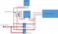
Looks like this controller uses an NTC type, I assume that I can't switch out types if the curves are all non-linear and different, seems like it would be designed to work with a specific thermister? Also, I am not sure what you mean by "RTD-100 is 2 wire device requiring a 3 or 4 leads".

Edit: Not sure what that upload showing at the bottom is all about. I didn't upload anything. Ignore it.
 

Attachments

wayneh

Joined Sep 9, 2010
18,111
Also... a quick, somewhat stupid question/clarification. All of my previous exercises with building temperature controllers used thermocouples for sensing the temperature, so I am new to thermistors. In this case, the thermistor would be acting like the thermocouple and sensing the temperature of the environment to be controlled, right? So the thermistor should go inside the enclosure and then be wired back to controller (which will ideally be outside the enclosure), correct?
Correct.

I think what you want is actually very simple. You just need a thermostat to control the TEC, plus a way to change the setpoint (or toggle to another thermostat) by time of day.

What sort of control do you want for the time? The simplest is like a cheap lamp timer, where you have some hours of the day that are "on" and the rest are off. The most complex approach changes the timing with the season. My outdoor gaslights, for instance, turn on at sunset and go off 6 hours later. They uses a combination of a photocell and a timer to accomplish this.

Assuming you just need only the simple lamp timer approach, the question is what is the simplest way to accomplish this. I'm thinking a $5 lamp timer is tough to beat with a DIY solution. I haven't worked out the details but I'm thinking you could wire it so that when the timer clicks on or off, this changes the set point of your thermostat. The thermostat just needs a reference voltage to establish a temperature set point. It compares the thermistor output to this reference and decides whether to turn the TEC on. So you need a circuit to convert the on/off output of a lamp timer into two reference voltages for your thermostat. This is not hard!
 
Also, I am not sure what you mean by "RTD-100 is 2 wire device requiring a 3 or 4 leads".
An RTD is another temperature measuring device. Theory is here: http://www.omega.com/techref/rtd-measurement-and-theory.html

They are low value resistances, I believe about 100 ohms at room temperature, therefore the effect of lead resistance needs to be removed. More like force and sense terminals. So, two wires are attached to each lead. One carries current and the other measures voltage. The voltage measuring leads don't have a voltage drop.

3-leads also work,because the missing 4th lead drops the same voltage as the missing 3rd one, so 2x the 3rd lead drop as long as the wire sizei s the same.

Some sensors are thermister, thermocouple, RTD's, and diode. Thermisters are seen in low cost moderate temperatures, Thermocouples are seen in high temperature applications. Type T is used in cryogenic and room temperature applications. Rugged, but expensive. RTD's have very good limit of error (Rare, but I've used them). Diode sensors generally have an output proportional to absolute temperature mV/deg K. It's also used in cryogenics. Used them all in a semiconductor lab where I worked.

Thermocouples are selected based on their temperature range and environment. Familiar with J,K, R, S and T.
 

wayneh

Joined Sep 9, 2010
18,111
And just FYI, there are integrated circuit thermometers such as the LM35. Some have digital outputs but the LM35 produces a voltage in proportion to temperature. These ICs have features that make them much easier to use in certain applications. In particular they are pre-calibrated.
 

Thread Starter

xiphius

Joined Feb 13, 2017
18
Yes, I am trying to keep it as simple as possible. This is my new thinking in terms of setup (diagram attached) - get 2 PWM TEC controllers and tune the set points for night/day, then wire them through an SPDT relay that is actuated by a 12V programmable timer switch. Then I could swap between the outputs from each controller based on time. I could build the whole thing for like $70 (since SPDT relays and 12V timers are dirt cheap), which would be about the same as getting a ramp/soak controller which I would then have to figure out and possibly modify. Plus, this way I will have a separate set screw for the night and day control and can adjust separately and slightly as necessary to achieve warmer or cooler temperatures.

Thanks for all the input on sensors! Really informative and I am learning a lot here. I toyed with the idea of a photocell, but that seems a bit excessive since I won't be using natural light, but LEDs, for the growth chamber. So any seasonal changes in lighting will be artificially set by me and I could just as easily change a timer for the temperature controller at the same time rather than trying to link the controller to the lights via a photocell.
 

Attachments

You can't parallel the thermistors. You would have to use two of them.

FWIW: There are astronomical timers which can turn stuff off +- sunset or fixed times.

True. Automotive relays are cheap. They are available with sockets. See http://www.parts-express.com/Search.aspx?keyword=automotive relay and socket&sitesearch=true

The 12 VDC timer may be hard to source. If there is no LED, you may want to use one to indicate which module is active. You can alaos use a LED and resistor to indicate relative voltage applied to the TEC as well.

I think I would buy one module and see if there are any other issues before continuing, but then $30.00 is cheap.
 

Thread Starter

xiphius

Joined Feb 13, 2017
18
1. Thanks! Yeah, didn't think that one through. but getting 2 of them is easy/cheap.

2. Yeah, and Jameco electronics has 12V, 10A SPDT relays for like $2.00. Hadn't thought about automotive relays, I'll check local autoparts stores to see if I can find them locally.

3. 12 V DC timer switches are all over Amazon and elsewhere, not sure why you think this will be hard to source unless there is some reason why something like this will not work? (link - this particular one can handle up to 16A) Something like this is what I was thinking of using for the timer.

4. Yes, that was the plan. I always try and be cautious. At the beginning, it would be sufficient to just control the night temperature, I can add functionality to control the day temperature after I confirm that it will work for nights.

Also, adding LEDs is a great idea!
 
Typical USELESS Amazon info: 192 Watts one place and something else in another.

Power Source DC
Voltage 12 volts
Wattage 192.00

and
2. Rated Voltage: 12V DC
3. Contact Capacity: 16A
4. Power Consumption: no more than 2w

For the SAME product and on the SAME page. Never believe Amazon specs.

The word is Astronomic: http://www.intermatic.com/en-us/timer-controls/plug-in-timers/dt620
It computes the time for sunrise and sunset. It's possible, that in your application it isn't important.

You;d probably like one that say came on a dawn and stayed on for x-hours. At home, I use one to come on about 1/2 hour after sunset and off at 11:00 PM.

A reminder to put suppression diodes on the DC coils of the relays.
 

Thread Starter

xiphius

Joined Feb 13, 2017
18
Sunrise and sunset computation would definitely be very useful. That way the seasonal change in temperature/lighting would be automatic without me having to reset the timer every few months. Didn't even know they made sunrise/set timers.

Thanks for the heads up about adding a suppression diode for the relay coil. I didn't know about that. Just looked it up and will be sure to add one. I see several different configurations, but it looks like the simplest is to just wire in a 12 V zenner diode reverse biased in parallel. Seems like the other configurations are to maximize the switching speed, but in this case, it's not critical that it be super super fast.

Also, crazy thought - any reason I can't run the peltier directly off of a PWM DC motor speed controller? I know that this wouldn't let me measure and feed back the temperature, but the enclosure will be very well insulated and in an environment where the outside temperature will be relatively constant from day-to-day (so the TEC controller would probably be spending most of its time running at a constant signal anyway). So, it seems to me that it might sufficient to use two DC motor speed controllers (something like this) and set the day/night temperature initially by using guess-and-check - dial it a little and let the temperature stabilize until I find the right position to achieve the temperature I want - which would hopefully be relatively stable since rapid and/or large fluctuations inside or outside the enclosure are not expected to occur. The rest of the circuit would be the same (switching relay and timer). It wouldn't be as good as using the TEC controller, but it would be MUCH cheaper (since these speed controllers are only like $6 apiece instead of $30 - although $30 is still pretty cheap and well within my budget). If this is sufficient, then I could have the whole system up and running for ~$30-40. If it's not sufficient, then I am only out ~12 for the speed controllers and I can buy the TEC controllers and add them in like I was originally thinking. Might be a good place to start, and then graduate up to the TEC controllers if needed.

Or, in your experience, would driving the TEC at some constant PWM signal not be sufficient to maintain a relatively stable temperature (assuming constant outside temperature and very good insulation on the chamber)?

Edit: or a controller like this instead. If you read the fine print on the one I initially linked it says that it can't be used as a voltage regulator, so that one was probably a bad choice...
 
Last edited:
1. They are a LOT better than a photocell.

2. It's not a zener diode for the coils, just a regular diode. Make the PRV to be about 2x 12V, so a 50 V diode would suffice. In a car, 200 V for other reasons. The diode, in general, protects what's driving it, but may protect the power supply. The closer to the relay coil, the better. Just watch the orientation.

3. That's what I said early on, just run open loop. If the sink temperature (outside the controlled environment) is constant, then you may be good to go. That's what I did most of the time, but instead of PWM, there were DC power supplies available.

Note: Going full-circle is good. Go for the gold standard and scale back. What you buy initially may influence the gold standard if you require it. It's, sort of, a balance. Note, I didn't throw out a solution, but the tools to find one.
 

wayneh

Joined Sep 9, 2010
18,111
You don't need PWM. You can get to ±0.5°C or so with a simple on/off thermostat. I added an op-amp to increase the voltage of the LM35 output, for instance instead of 0.15V at 15°C, to 1.5V, and got steady-state control to within ~0.1°C with just on/off control.

Go simple until you're proven you need more complexity. You won't.
 

Thread Starter

xiphius

Joined Feb 13, 2017
18
Awesome. Thank you so much.

1. Yeah, read a lot about them. I think I am definately going to incorporate one. They sound really nice and I can use these features.

2. Good to know. Strange... most of the schematics I have seen show a zenner diode of ~=coil voltage. But on reading further I guess that having =coil voltage is the MINIMUM, so having it be bigger is better.

3. Sorry to rehash. I guess it didn't "click" when I read your post earlier. At least now I have a grasp on how to handle it if this isn't good enough, but I'll start here.

This is exactly why I am here. I was never looking for anyone to design the system for me. Just looking for advice, insight, and to learn.

wayneh - ON/OFF thermostats were my original idea (attached diagram in my first post). KeepItSimple seemed pretty convinced this strategy wouldn't work well, hence all the discussion of PWM. Plus, getting a PWM DC motor speed controller would be about the same cost as getting a 12V DC ON/OFF thermostat anyway.

I'm curious what ON/OFF thermostat you used with the LM35 though, if you remember. I'll check it out.
 
Last edited:
2. Good to know. Strange... most of the schematics I have seen show a zenner diode of ~=coil voltage. But on reading further I guess that having =coil voltage is the MINIMUM, so having it be bigger is better.
The voltage that ends up across the coil is a stored voltage due to the inductance of the coil. It is in fact, the same polarity.

Two useful rules: 1. The voltage across a capacitor can't change instantaneously and 2) The the current through an inductor can't change instantaneously are just plain useful.

2x the rating is always a good number to start. The diode PIV (peak inverse voltage) rating CAN be non-destructive IF the current is limited.

FYI: Schottky diodes have a smaller voltage drop. They are made with just a metal and a semiconductor - no PN junction. We use 0.6 or 0.7 V as an estimate of the voltage drop of a silicon diode. Germanium, an early unstable semiconductor was, Ithink, about 0.3 V.

The automobile electrical system has been described as having -200 V transients and +50 Volt ones, so that's why the automobile environment gets special treatment.

Switches/relays have specific characteristics for AC and DC switching. Some relays I used for (15 kV @ 3 A) could not be switched with the power on. There is a "wetting current" or the smallest current that can be switched reliably. Oxides build up on the switches unless exotic materials are used. So, relays designed to switch 100 Amps, don't do well at 1 Amp.

AC contacts can be protected with bidirectional ZnR's or TVS devices. Sometimes a simple capacitor is used. Since Ac turns off periodically,an arc is easy to suppress.

The direction switch on a ceiling Fan really should not be switched when the fan is turning.

==

Another piece of useful info is with wiring: 1) twisting reduces EMI (Electromagnetic Interference) and 2) Shielding reduces RFI (Radio Frequency Interference).

When a wire is twisted, EMI induces a voltage in the wires, the twist couples them and the current they are carrying is likely in opposite directions or differential, thus the noise tends to cancel. Shielding prevents RFI. The shields should be grounded at one end only to avoid ground loops.

==

This http://www.thermoworks.com/RT8100MAT MAY be useful for you. I have a couple. The suction cups don;t really work and you really have to walk by it to notice. But useful to know how long, it's been above a value. It's not a logger.

==

LM35: Many of the industrial temperature controllers have so many different inputs, it's not funny. Those that accept thermocouples,it's sometimes easy to add a 10 mV, 50 mV or 100 mV full scale or effectively the input without cold junction compensation. The LM35 makes it easy to design your own bank/bank controller.
 

Thread Starter

xiphius

Joined Feb 13, 2017
18
KeepItSimple -

Good info! Thanks! I didn't know about wire twisting reducing interference.
Thanks for this, but I have a couple USB temp/humidity data loggers that I am going to use to test and monitor the enclosure.

wayneh -

Really cool looking project! Admittedly though, building my own thermostat from scratch was a bit more involved than I was hoping to get here. Still looks really cool though. How big was your chamber approximately? It looks like our objectives are/were fairly similar (except the whole 2-set point switching thing).

I have put a fan/heatsink combo on both the hot and the cold side of the TEC. I have also insulated the space between the two heatsinks and either insulated or used non-conductive materials for all attachments between them to try and mitigate the problem you mention of heat flowing back to the cold side from the hot side (which I can see being a big drain on the TEC's ability to effectively cool even a small space).
 
Last edited:

wayneh

Joined Sep 9, 2010
18,111
Really cool looking project! Admittedly though, building my own thermostat from scratch was a bit more involved than I was hoping to get here.
It's actually pretty simple if you eliminate the op-amp I used to get greater precision. But yeah, there's no reason you can't use off-the-shelf stuff.

Still looks really cool though. How big was your chamber approximately? It looks like our objectives are/were fairly similar (except the whole 2-set point switching thing).
From memory only, it's about 4" square and 1" high. The objective was to hold a set temperature, which it does very well. No PWM in sight.

One issue with PWM is thermal shock to the TEC from the pulsing. I don't remember the details because I ended up not using PWM, but some frequencies are fine while some can be damaging. I think the fancy controllers use a low-pass filter between the PWM and the TEC, to reduce the stress on it.
 

Thread Starter

xiphius

Joined Feb 13, 2017
18
Yeah, I had read about that. Seems to not to be too much of an issue except maybe in the longterm (multiple years of use). A study conducted a while back and looking at PWM driven TECs between 0.1-10k Hz concluded:

"There was only a slight degradation in the ACR (AC resistance) of all of the TEM’s tested. It can be concluded that all of the PWM frequencies tested so far have had little impact on the ACR to cause concerns regarding reliability. The changes in ACR with respect to frequency are still too small to make any determination of an optimal frequency for a PWM controller since all patterns regarding this are statistically insignificant. Testing should be extended to determine if any statistically significant patterns will emerge."

Source: M. J. Nagy and S. J. Roman, "The effect of pulse width modulation (PWM) on the reliability of thermoelectric modules," in Thermoelectrics, 1999. Eighteenth International Conference on, Baltimore, MD, USA, 1999.

I am more concerned about the dramatic drop in efficiency when using PWM to drive a TEC then I am about thermal cycling causing mechanical failure. It's possible that with PWM I will not be able to achieve the temperature drop that I would like. I won't know for sure until I figure out what the maximum temperature drop I can achieve is. I hope to run this test tonight. The last part I need to power the TEC should be arriving today, then I can just run it for a while at max power and see how cold I can get things in the first place.

I could also just add a filter like you suggested since those are pretty easy to build.
 
Last edited:

wayneh

Joined Sep 9, 2010
18,111
The last part I need to power the TEC should be arriving today, then I can just run it for a while at max power and see how cold I can get things in the first place.
Ooh, be careful how you run that. At max power, it's easy to drive the hot side above the safe temperature and ruin your TEC. Some commercial coolers will put a thermistor on the TEC itself (it can be on either side, just at different set points) to shut down power in case of this happening, for instance if a fan dies.

I'd start the thing up at maybe half of max current, and then validate that everything is under control and that your heat dissipation scheme is actually doing the job. The ∆T that the TEC achieves depends on the current supplied. The temperature on the cold side is (or should be) a predictable function of the temperature of the hot side and the supplied current. TEC efficiency is higher at low current (and thus lower ∆T) but of course low current limits the ∆T. If you need a low temperature on the cold side, there may be no way to achieve it without going to high current and low efficiency. This is why you will sometimes see stacked TECs.
 

Thread Starter

xiphius

Joined Feb 13, 2017
18
Thanks for the heads-up and warning. Yes, I would not operate it without the heatsinks and fans also running (especially not at max power). I will be monitoring the temperature and current to make sure everything is working as predicted and, if not, I will pull the plug.
 

Thread Starter

xiphius

Joined Feb 13, 2017
18
Ran a successful test this weekend and it looks like at max power I can get a dT of about 20 F (not bad, especially considering I was forgetting to account for dew point and phase changes, which chew up a lot of power). Temperature changes pretty slowly, so open-loop is probably going to be fine.

As I get started setting up the control system, I had a quick question about building a low pass filter for the PWM, specifically about sizing the resistor. The filter is probably a little bit overkill, but I figure it seems easy to add, so I may as well go ahead and do it to help improve the efficiency and increase the longevity of the TEC (see new attached diagram). So it is a resistor in series and a capacitor in parallel on the output of the relay (from the PWM controller) to the TEC.

The plan is to use an 0.5 ohm resistor and a 1000 uF capacitor, which should give me a decent compromise between response time and a steady output voltage. So my question is this - since the maximum amperage of the TEC is 8 A, I would need a resistor rated for 50 Watts (since power = current^2 * resistance... 64 A*0.5 ohm = 32 watts ), correct? I found a 0.5 ohm, 75 watt resistor that I was thinking of getting since it seems like having it rated higher than needed would not be a bad thing. Unless I am thinking about this wrong - I haven't worried too much in the past since it's mostly been much lower amperage and the little, standard banded resistors have always been good enough, here I would imagine those would melt or blow out.
 

Attachments

Top