 Facebook
 Google
 GitHub
 Linkedin
Hi all,
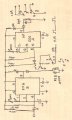
I have a 556 timing circuit that runs the two timers (A and B) in sequence. The two timers actuate DPDT relays.
Timer A is triggered using a PIR sensor and controls a 12VDC, 10A DPDT relay. One side of the relay is used for switching power to an external device. The other side is used for triggering timer B. When timer A runs out, the NC/Common connection on one side of the 10A relay triggers timer B.
Timer B controls a 12VDC, 2A DPDT relay that is used to interrupt the signal from the PIR sensor that triggers timer A. This effectively "locks out" the sensor so that the circuit can't be re-triggered until both timers have run out.
Here's the problem: when switching DC power through the 10A relay, the circuit behaves normally. The timers run sequentially without any odd re-trigger events or overlapping. When switching AC power through the 10A relay, I sometimes get overlapping of the timing (timer B starts before timer A runs out, or timer A continues to run after timer B starts - I don't know which). Sometimes timer A will re-trigger itself 2-3 times, then time out normally, allowing timer B to start.
The AC current being switched is <0.5A. The DC current loads have been as high as 5A with no behavior problems. Clearly, the problem seems to be coming from the AC loads.
I have 1N4148 diodes across the relay coils, and a 1N4001 on each output pin of the 556. Should there be diodes on the 556 trigger input pins as well? Could switching AC power through the 10A relay generate a magnetic field that is interfering with operation of the 556? I know that magnetic fields can't be insulated, but is there a way to contain or re-direct the field away from the 556? Re-location of the 556 or the relay isn't an option - the boards are already printed. I can post pics of the board on Monday if needed. All advice greatly appreciated.
Gary


")


