Facebook
 Google
 GitHub
 Linkedin
greetings, this is my first post on the website.
in the last few weeks i've begun setting up a small electronics kit (breadboard, multimeter, etc), and for my first project, i am trying to make a bench power supply.
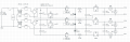
i've attached a 'rough' schematic to this post. i say 'rough' because i haven't included any of the feedback circuitry for the voltage regulators, or circuitry for the volt and amp meters.
i just want to make sure that there aren't any gleaming errors/design flaws that i haven't noticed yet.
the goal of this power supply is to generate a floating voltage supply (like most bench supplies), but also a dual tracking +ve and -ve supply for running dual supply op-amps. i want up to 20v, and +20, -20 on the dual line. ideally, i would also like to draw 1-2 amps from the lines.
i decided to cascade a buck converter with a linear supply so that the buck converter could do the bulk of the voltage control, with the linear supply being used to remove the ripple. i didn't want to use a linear by itself because i don't want to deal with massive heat sinks.
the volt and amp meters will be controlled by 2 pic micro-controllers, 1 for each floating voltage.
my main questions so far are:
1. is the linear regulator necessary? will a few more caps on the output of the buck reduce the ripple to the same extent? is it even worth the trouble? (i'm not doing audio work, just general electronics, micro-controllers, op-amps, etc.)
2. how important is power factor and passive filters between mains and the transformer? i have an old atx power supply that i could pull the filter out of. is it worth it, and would it even work with a lower current load than it was designed for?
3. for the +ve and -ve lines, is it okay to use a full wave diode bridge with one of the ac input lines floating like in the circuit diagram? it should 'theoretically' still be the same as 2 diodes, each half wave rectifying the AC into the +ve and -ve DC lines. right? right!?
4. how sensitive are op-amps to changes in their supply voltages? for example, say i'm using an op-amp to measure the millivolt difference accross a current sense resistor, if it's supply voltages are unregulated, will it still be reasonably accurate? i guess the solution to this would be to create regulated 18v and -18v lines, or something like that. :/
5. anything i've missed, opinions and suggestions are all welcome.
in the last few weeks i've begun setting up a small electronics kit (breadboard, multimeter, etc), and for my first project, i am trying to make a bench power supply.
i've attached a 'rough' schematic to this post. i say 'rough' because i haven't included any of the feedback circuitry for the voltage regulators, or circuitry for the volt and amp meters.
i just want to make sure that there aren't any gleaming errors/design flaws that i haven't noticed yet.
the goal of this power supply is to generate a floating voltage supply (like most bench supplies), but also a dual tracking +ve and -ve supply for running dual supply op-amps. i want up to 20v, and +20, -20 on the dual line. ideally, i would also like to draw 1-2 amps from the lines.
i decided to cascade a buck converter with a linear supply so that the buck converter could do the bulk of the voltage control, with the linear supply being used to remove the ripple. i didn't want to use a linear by itself because i don't want to deal with massive heat sinks.
the volt and amp meters will be controlled by 2 pic micro-controllers, 1 for each floating voltage.
my main questions so far are:
1. is the linear regulator necessary? will a few more caps on the output of the buck reduce the ripple to the same extent? is it even worth the trouble? (i'm not doing audio work, just general electronics, micro-controllers, op-amps, etc.)
2. how important is power factor and passive filters between mains and the transformer? i have an old atx power supply that i could pull the filter out of. is it worth it, and would it even work with a lower current load than it was designed for?
3. for the +ve and -ve lines, is it okay to use a full wave diode bridge with one of the ac input lines floating like in the circuit diagram? it should 'theoretically' still be the same as 2 diodes, each half wave rectifying the AC into the +ve and -ve DC lines. right? right!?
4. how sensitive are op-amps to changes in their supply voltages? for example, say i'm using an op-amp to measure the millivolt difference accross a current sense resistor, if it's supply voltages are unregulated, will it still be reasonably accurate? i guess the solution to this would be to create regulated 18v and -18v lines, or something like that. :/
5. anything i've missed, opinions and suggestions are all welcome.
Attachments
-
 106.4 KB Views: 386