Need Advice about two different GNDs.

Thread Starter

Mussawar

Joined Oct 17, 2011
158
Hi,
Hope you are all fine.
Two different power supplies are used in my design.
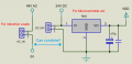
1) 24V DC. Coming from a SMPS and is used for small relays and is further regulated to 5V for a Micro controller.
2) 48V AC. Coming from a transformer and is used for some Magnetic Contractor coils. .
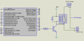
(Please see attachment for diagram segment)
My question is, can I use a common ground for both power supplies? As shown in my Schematic?
Thanks for any help.
 

Attachments

ronsimpson

Joined Oct 7, 2019
4,658
I cannot see the larger picture. How are you turning on/off the 48V coils? This will make a difference.
Probably you should connect the two grounds. Probably the micro turns on a MOSFET which powers the coils. This would require the grounds to be connected together.
You should think about where the two grounds will get together. Maybe connect the 48V ground near the MOSFETs and coils.
 

Thread Starter

Mussawar

Joined Oct 17, 2011
158
I cannot see the larger picture. How are you turning on/off the 48V coils? This will make a difference.
Probably you should connect the two grounds. Probably the micro turns on a MOSFET which powers the coils. This would require the grounds to be connected together.
You should think about where the two grounds will get together. Maybe connect the 48V ground near the MOSFETs and coils.
Thanks for reply. A Micro Controller drives small 24V DC relays through a transistor. These relays then drive 48V AC Coils. Hope attachment makes it clear.
 

Attachments

Last edited:

ronsimpson

Joined Oct 7, 2019
4,658
Now I see. Sorry I did not see the "AC".
Keep the AC isolated from the micro!
----edited----
It will work either way but I would keep the AC isolated.
 

Thread Starter

Mussawar

Joined Oct 17, 2011
158
Now I see. Sorry I did not see the "AC".
Keep the AC isolated from the micro!
----edited----
It will work either way but I would keep the AC isolated.
I also added a second schematic to make it more clear.
AC Coils voltage might be variable. It can be 48VAC. 110VAC, 220VAC or 24VDC. (Subject to availability) I want to give user a free hand to use what ever voltage coils are available. For this, I have to use two different power rails.
If user uses 24VDC coils then he can use only one PS by just putting a jumper at 24VDC and other power supply; then he GND remain same. But as you suggested, better to keep both separate especially when using 220VAC coils.
I greatly appreciate your help. Thanks.
 

Thread Starter

Mussawar

Joined Oct 17, 2011
158
I would was, WHY would you want to connect the grounds together? I dont think you would gain anything.
For the sake of ease.
AC Coils voltage might be variable. It can be 48VAC. 110VAC, 220VAC or 24VDC. (Subject to availability) I want to give user a free hand to use what ever voltage coils are available. For this, I have to use two different power rails.
If user uses 24VDC coils then he can use only one PS by just putting a jumper at 24VDC and other power supply; then the GND remains common. and need only one jumper to mix both power supplies.
 

meth

Joined May 21, 2016
299
For the sake of ease.
AC Coils voltage might be variable. It can be 48VAC. 110VAC, 220VAC or 24VDC. (Subject to availability) I want to give user a free hand to use what ever voltage coils are available. For this, I have to use two different power rails.
Sorry if I dont follow something, but how can AC Coils be 24VDC?
 

Thread Starter

Mussawar

Joined Oct 17, 2011
158
Sorry if I dont follow something, but how can AC Coils be 24VDC?
Sorry about my English grip. Theses coils are Magnetic Contractors and might be AC or DC (subjects to availability) That's why I am driving them through relays.
 

meth

Joined May 21, 2016
299
No problem, now I understand.
To be honest I don't think it is a good practice to do this.
Upon choosing, maybe find a method where the selecting mechanism switches the both ends of the supply (double pole), instead only the "plus" of the supply voltage. That way you would be 100% safe.
Anyway, you can always try in a safe environment (some test bench with circuit breakers) and see what happens, but again, if you do this for a client as you said, do not mix the AC and DC supplies.
 

Thread Starter

Mussawar

Joined Oct 17, 2011
158
No problem, now I understand.
To be honest I don't think it is a good practice to do this.
Upon choosing, maybe find a method where the selecting mechanism switches the both ends of the supply (double pole), instead only the "plus" of the supply voltage. That way you would be 100% safe.
Anyway, you can always try in a safe environment (some test bench with circuit breakers) and see what happens, but again, if you do this for a client as you said, do not mix the AC and DC supplies.
Advice regarded.
Yes, it's really good to be safe as compare to ease. I will keep both poles separate. At the cast of just one extra jumper my design will be safe. Also I get in my mind about inductive noise might interrupt Micro Controller function. So isolation is the better way.
Thank you very much for your time.
 

MisterBill2

Joined Jan 23, 2018
27,258
OK, I have read thru and see why there is a question.
The answer about tying the commons to each other is "Possibly".
The caution is that it will be a poor choice to have any conductors carrying current for both systems, because that will introduce unintended voltages in each system caused by currents in the other system. So if it would be done to save wiring, I suggest caution and avoiding interactions.
You might get away with it and have no problems at all. OR, maybe not.
 

MaxHeadRoom

Joined Jul 18, 2013
30,588
. Most of the fellows logically advised to not to do this and keep AC and DC grounds separate.
Thanks for your precious time.
I am not sure why that would be?
All the industrial control systems I have implemented over the years, I have tended to reference all the power commons, to earth GND common where possible.
Also for e.g. The DIY CNC systems that use a PC for the control pgm, start out by connected to earth GND by virtue of the PC PS being GND connected also.
 

MaxHeadRoom

Joined Jul 18, 2013
30,588
BTW, the normal practice with earth GND connection, is to set up a Star point GND plate in the enclosure where every ground route is terminated, together with the actual Earth GND conductor.
 

Thread Starter

Mussawar

Joined Oct 17, 2011
158
I am not sure why that would be?
All the industrial control systems I have implemented over the years, I have tended to reference all the power commons, to earth GND common where possible.
Also for e.g. The DIY CNC systems that use a PC for the control pgm, start out by connected to earth GND by virtue of the PC PS being GND connected also.
Hi MaxHeadRoom, Thanks for reply.
Using a common GND for different level DC sources (e.g 24V dc and 10V dc) is quite common. In my case, however, first source is DC 24V and the second source might be AC or DC. In this case, is it safe to make both GNDs common?
Best regards.
 

MaxHeadRoom

Joined Jul 18, 2013
30,588
Hi MaxHeadRoom, Thanks for reply.
Using a common GND for different level DC sources (e.g 24V dc and 10V dc) is quite common. In my case, however, first source is DC 24V and the second source might be AC or DC. In this case, is it safe to make both GNDs common?
Best regards.
It may be possible, depending on how exactly the different systems differ in design & function & relation to each other, but in many cases it could quite easily be possible.
 
Top