Hello all,
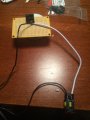
I have built a circuit which uses this automotive relay: https://www.amazon.ca/MICTUNING-5-P...&ie=UTF8&qid=1495023392&sr=1-1&keywords=relay along with a momentary switch (to activate the coil) and a 12VDC 1 A wall wart.
Everything worked great for a while, but the client is having mysterious issues after about 40 hours of use. I cannot troubleshoot effectively unfortunately because the unit is currently in storage.
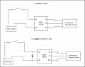
I have attached an image of my original circuit - some things to keep in mind:
I have built a circuit which uses this automotive relay: https://www.amazon.ca/MICTUNING-5-P...&ie=UTF8&qid=1495023392&sr=1-1&keywords=relay along with a momentary switch (to activate the coil) and a 12VDC 1 A wall wart.
Everything worked great for a while, but the client is having mysterious issues after about 40 hours of use. I cannot troubleshoot effectively unfortunately because the unit is currently in storage.
I have attached an image of my original circuit - some things to keep in mind:
- I do not know how to tell + from - on the PSU, and do not know the standard for black and white on the relay harness, and do not know which way the diode must be pointing if it is required. I do have a voltmeter. if you think the lack of diode caused the issue, I will be rebuilding the circuit, so any indication on how to properly do this would be phenomenal.
- The PSU is connected only to the momentary switch and the relay coil - no power is being applied across the switching contacts of the relay (30 / 87 / 87a).
- My hope is that wired like this, the diode isn't really necessary, but will redo this if needed of course.
Attachments
-
 77.1 KB Views: 52