NE555 Timer with Relay (help)

Thread Starter

beingsallu

Joined Jul 10, 2012
18
Hello every one I am noob in electronic
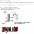
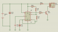
I want to make 555 timer circuit to driving relay like it sound tik.. tik...tik..tik... with using BC547 Transistor ...

so any one know how to made this circuit so please tell me daigrame of circuit.

i am attaching a photo of circuit.
 

Attachments

Bernard

Joined Aug 7, 2008
5,784
Nit picking: Sounds like tic- toc - tic - toc. Relay will be energised about 50% of period, so if battery life is of consern, an added diode, cathode to pin 6, across 100k, would make tic a quick relay close-open @ 5% duty.
 

Thread Starter

beingsallu

Joined Jul 10, 2012
18
is this circuit works fine on breadboard
beacause some where i read that BC547 transistor not works properly on breadboard
 

absf

Joined Dec 29, 2010
1,968
Should be fine. I did a lot of this type of stuffs on breadboard and so far I didn't encounter any problems. As long as you keep the wires as short as possible.

Allen
 
Last edited:

#12

Joined Nov 30, 2010
18,224
A one second oscillator will NOT run into parasitic picofarad problems.
You're completely safe on a protoboard.

I did one of these 20 years ago for a metronome. I used a capacitor to couple the output (to reduce the duty cycle). 50% duty cycle on the 555 but only a capacitor charge worth of current arrived at the speaker.
Slightly different sound than Bernards. His diode solution will work. I am not arguing against it, just offering an alternative for the purpose of allowing subjective preferences.
 
Last edited:

#12

Joined Nov 30, 2010
18,224
The timer will work when you give it 12 volts but you have to re-calculate R15 and R19 for the higher voltage. I think R15 should be about 1800 ohms and R19 will not be included.
 

Audioguru

Joined Dec 20, 2007
11,248
The transistor is not needed. The 555 has plenty of output power to drive a relay.
The relay needs a diode across its coil to arrest the few hundred volts it tries to generate when it turns off.
 

Thread Starter

beingsallu

Joined Jul 10, 2012
18
I manage to use up all the components of your PCB. Here's the schematic with the relay that will provide you with the "tick tick tick"

Allen
when pin 3 connected with resistance to Bace of BC547 (transistor)
relay doesnt work like tik tik :(
but when pin 3 connected direct to Bace of BC547 (transistor)
relay do tik tik
and

when Emitter of BC547 (transistor) connected negative side of battery

then relay doesnt work tik tik :(
but
when Emitter of BC547 (transistor) does not connected any where relay wrk like tik tik

whats wrng with the circuit ??
 

Audioguru

Joined Dec 20, 2007
11,248
The transistor is not needed. Since the relay coil does not have an important diode across it then the transistor you used is probably destroyed.
You changed the connections of the transistor so that its emitter is not connected then it is simply a diode (base to collector) in series between the output of the 555 and the relay coil.

Or maybe you mixed up the pins of the transistor so they were connected wrong.

Make the circuit like this:
 

Attachments

Thread Starter

beingsallu

Joined Jul 10, 2012
18
The transistor is not needed. Since the relay coil does not have an important diode across it then the transistor you used is probably destroyed.
You changed the connections of the transistor so that its emitter is not connected then it is simply a diode (base to collector) in series between the output of the 555 and the relay coil.

Or maybe you mixed up the pins of the transistor so they were connected wrong.

Make the circuit like this:
I am using 12v battery and 12v relay
and i knw transistor is not needed but
i want to drive relay through BC547
 

Audioguru

Joined Dec 20, 2007
11,248
You are using the transistor as an inverter. Why?

Since your relay and power supply are both 12V then the 10 ohm resistor is not needed.
 

Audioguru

Joined Dec 20, 2007
11,248
How many times must I tell you that your transistor is probably destroyed because you did not connect a diode across the relay coil.

When the transistor turns off then the inductance of the relay coil generates a few hundred volts that destroys the transistor when there is no diode.

Why do you need the transistor to invert the signal from the 555?

Here is the relay connected differently to the 555 and the 555 inverts:
 

Attachments

Thread Starter

beingsallu

Joined Jul 10, 2012
18
How many times must I tell you that your transistor is probably destroyed because you did not connect a diode across the relay coil.

When the transistor turns off then the inductance of the relay coil generates a few hundred volts that destroys the transistor when there is no diode.

Why do you need the transistor to invert the signal from the 555?

Here is the relay connected differently to the 555 and the 555 inverts:
the 555timer circuit connect with relay and relay connected with high voltage plate (which is use in mosquito killer racket) and High voltage plate and relay connected with naked thik copper wire which may produce high voltage frequnce
 

Audioguru

Joined Dec 20, 2007
11,248
We don't use "mosquito killer rackets" in my country so I have never seen the circuit.
Your photo shows a voltage stepup transformer, not a relay.

I found the circuit in Google. It is completely different to your circuit:
 

Attachments

Thread Starter

beingsallu

Joined Jul 10, 2012
18
We don't use "mosquito killer rackets" in my country so I have never seen the circuit.
Your photo shows a voltage stepup transformer, not a relay.

I found the circuit in Google. It is completely different to your circuit:
dude this High Voltage PCB is a part of circuit
 

Thread Starter

beingsallu

Joined Jul 10, 2012
18
but why BC547 is not working even with LED
collector pin connected with resistor and pin 3 of 555timer IC
base connected with LED positive leg and nagetive Leg of led connected with negative side of battery
but when i connected Emitter to negative side of battery LED does not flashing :(
 
Top