NAND gate purpose in this circuit

Thread Starter

brightnight1

Joined Jan 13, 2018
97
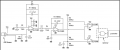
I was wondering if someone could help me determine the purpose of the NAND gate in this PIR circuit. I know the NAND gate truth table and how it works, what it outputs, etc, but I don't understand its role in this circuit and why it's optional.

I posted a picture of the schematic with the NAND gate but it can also be found at the bottom of this datasheet:
http://www.st.com/content/ccc/resou...df/jcr:content/translations/en.DM00096551.pdf


Thanks in advance.
 

Attachments

ebp

Joined Feb 8, 2018
2,332
The circuit is a window comparator - the output is one logic level if the input is between two thresholds and the opposite level if the signal is above the upper threshold or below the lower threshold. I'll leave you to work out the details for that circuit.

Sometimes wired-AND (sometimes called wired-OR, but often erroneously) is used where the comparators are open collector and a passive pullup resistor is used (which is definitely a wired-AND = wired-NOR). Op amps are used in that circuit, so the outputs can't be connected together. Using a gate saves a pin and some code for the microcontroller.
 

dl324

Joined Mar 30, 2015
18,221
The NAND gate isn't optional. When the voltage to the opamps being used as comparators is outside of the window indicated below, the outputs will fight each other. The schematic below the one you posted doesn't make sense either.

I feel embarrassed for whoever drew that schematic. It should have been drawn more like this:
upload_2018-6-15_9-48-21.png vs this upload_2018-6-15_9-49-13.png

Layout the opamps and resistors symmetrically, and, more importantly, use the dot convention consistently.
 

ebp

Joined Feb 8, 2018
2,332
The gate output is shown going to a microcontroller. You don't need the gate if you are willing to use two processor inputs and implement the gate function in firmware. If you have a spare pin and code space available, this is more sensible than adding a gate unless you have a spare gate in a multi-gate package. This is the kind of circuit that finds its way into consumer electronics, and saving a couple of cents per unit can be worth it.
 

Thread Starter

brightnight1

Joined Jan 13, 2018
97
So the NAND gate is looking at a threshold voltage and the voltage of the PIR sensor, When the PIR voltage goes HIGH and "see's motion", the NAND gate outputs a HIGH to the uController? Do I understand that correctly? If that's the case I guess I thought that the Op amps were configured as an analog comparator to do that
Thanks for all the advice thus far!
 
Last edited:

dl324

Joined Mar 30, 2015
18,221
So the NAND gate is looking at a threshold voltage and the voltage of the PIR sensor, When the PIR voltage goes HIGH and "see's motion", the NAND gate outputs a HIGH to the uController? Do I understand that correctly?
How can we say without knowing the nature of the PIR sensor?

The opamp window comparator, which is oxymoronronic, feeds a NAND gate that outputs a LOW when the input is between the upper and lower threshold.
 

Thread Starter

brightnight1

Joined Jan 13, 2018
97
How can we say without knowing the nature of the PIR sensor?.
I assumed all PIR's acted the same way and someone here might know that and could "simulate" different states such as Motion or no motion and give an explanation of what the NAND gate is doing. I hope I'm understanding you correctly.
 

dl324

Joined Mar 30, 2015
18,221
I assumed all PIR's acted the same way
If they were all the same, there'd only be one part.

The only thing you can be certain that they have in common is that they Passively detect InfraRed light. Some might provide an analog output, some might be digital, output voltages could be normally HIGH or LOW, some good for long distances, some good for short distances, and they may have different operating voltage and current requirements.
 

Dodgydave

Joined Jun 22, 2012
11,395
So the NAND gate is looking at a threshold voltage and the voltage of the PIR sensor, When the PIR voltage goes HIGH and "see's motion", the NAND gate outputs a HIGH to the uController? Do I understand that correctly? If that's the case I guess I thought that the Op amps were configured as an analog comparator to do that
Thanks for all the advice thus far!
The Nand gate is being used as an "Or" (nor)gate for Low signal pulses from the Window Comparator. The window Comparator is centred at half the supply, and each input is offset above and below half supply, so that when the pir gets a signal, it's amplified by the two stages, then fed into the comparators for signal detecting, which gives you a low pulse from either of the op amp outputs, and these are Inverted by the Nand gate to give a positive pulse.
 
Top