Facebook
 Google
 GitHub
 Linkedin
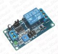
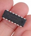
Each component and sub-component on a schematic has a reference designator. It is an unambiguous identifier used to identify parts in discussions, documentation, Bills of Materials, and pc board layouts. For example, I show the CD4011 as U1, with four internal components, U1A through U1D. In this way you can see the functions being performed (logic connections, signal flows, etc.) and track where those functions are located without having to find a datasheet and trace the pinout. And external module that connects to the circuit, like your touch module, is a judgement call. If there were more than one connecting to a larger circuit, I definitely would add an Xn ref des to each one.The NAnd gate has 4 outputs. I was referencing one of them as gate4. Specifically the one that sounds the buzzer.
Not to be too big a jerk about it, but in all of the universe there are only two types of schematics - those with reference designators, and those that are wrong.
ak