NAND gate outputs voltage

Thread Starter

ThomCircuit

Joined Feb 4, 2020
45
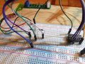
I supplied 5 volts to a touch sensor and it produces a latching 4volt trigger. I use that 4 volts to illuminate a dual red/blue led. I also send that 4v to the gate. When the right condition is met its output is sent to the led changing its color.
Now i send that output to a monostable configured 555 to play a 1/2 second beep from a 5v buzzer. It does work but the gates output is only 3v. So at only 3volts the speaker is not very loud. What should I do?
How do I Increase the voltage to at least 4v?
After I solve this I'm sending the trigger from the sensor and the output from the gate to an OR gate so it will sound the buzzer each time the led changes color.
This is simply an audio/visual feedback for when the button is pressed.
Thank you in advance
TB
 

Papabravo

Joined Feb 24, 2006
21,157
What kind of a NAND gate are we talking about? You may or may not be aware that a huge variety of gate types exist. The behavior you describe is no doubt compatible with the datasheet for the particular part you chose. You just neglected to read it -- a very common noob mistake
 

Thread Starter

ThomCircuit

Joined Feb 4, 2020
45
What kind of a NAND gate are we talking about? You just neglected to read it -- a very common noob mistake
Thank you for that. So is there no cure for my mistake? Can I fix this or should I look for a gate that would output its voltage the same as its input? What do you suggest? I have an ebay account and lots of time.
 

Papabravo

Joined Feb 24, 2006
21,157
Thank you for that. So is there no cure for my mistake? Can I fix this or should I look for a gate that would output its voltage the same as its input? What do you suggest? I have an ebay account and lots of time.
A NAND gate won't do that because there is an inversion. What kind of a NAND gate do you have? I can recommend an alternative if you tell me what you are working with. That shouldn't take too much time.
 

WBahn

Joined Mar 31, 2012
29,976
Please show a schematic of what you are currently doing. It is very hard to follow your description. For instance, you use the voltage from your latching trigger to illuminate an LED and then you claim that the output of this NAND gate is sent to the LED to change it's color? How?

Schematics are the language of electronics. Please provide one.

It will also help if you provide a clear description of what you are trying to achieve.
 

Thread Starter

ThomCircuit

Joined Feb 4, 2020
45
I dont have a drawing so I've attached a breadboard picture. I will draw one if it is necessary.
The gate is a CD4011
I have a 5v touch switch. When pressed it latches to the left side of the led turning it red. That 5v wire also goes to the gate (pin2) as high. Pin1 is connected directly to 5v. (High) When both pins are high the led is red. When pin1 is low and pin2 is high pin3 goes high and supplies voltage to the anode on the right side of the led making it blue. That's all it does.
My issue is the voltage output at pin3 is 3v. I'd like to get it to 4 or 5v so the 5v peizo speaker I connect it to will be louder than it is.
Perhaps I need better gates. I do not know one gates datasheet from another. I do understand voltage drop. I understand the quality or design of these gates may be the issue. Had no intention of using a speaker. It works very well as it is with the led. However I did create a beep circuit using an ne555. I created a pulse trigger to start the timer as well. I use the out from pin3 on the gate and connect it to the +positive rail of the 555 circuit. It works. It's just low in volume.
I'd like to know if the voltage can be increased to 4-5 volts after pin3. If not what would you guys suggest.
 

Attachments

djsfantasi

Joined Apr 11, 2010
9,156
You have to learn that a picture of a breadboard is a poor representation of your circuit. Depending on the angle of the picture, important details are obscured. Plus, a picture could represent many different circuits. The picture doesn’t effectively represent to IC being used. A picture of a 16 pin DIP IC could be one of many circuits.

The only way to communicate effectively what you have is with a schematic. You said you could draw one. I strongly suggest that you to do.
 

AnalogKid

Joined Aug 1, 2013
10,986
There is no power supply decoupling near the gate, and many of the unused inputs are left floating. this can cause the chip to act incorrectly, or fail.

The schematic does not have to be pretty, but it must be accurate. Show each of the four gates, and every connection to each pin.

ak
 

Thread Starter

ThomCircuit

Joined Feb 4, 2020
45
The schematic does not have to be pretty, but it must be accurate. Show each of the four gates, and every connection to each pin.
ak
I uploaded before I read your reply. None of the other pins are used. Just one of the 4 logic circuits + and - wires. 5 volt supply
 

WBahn

Joined Mar 31, 2012
29,976
Forget about this circuit and what it does or doesn't do.

Pretend you walk into Bob's Circuit Design Emporium and All Night Video Rental and you went up to Bob and said, "I need you a circuit that does the following things."

What are those things?

It sounds like you want to have a button, a light, and something that makes sound. Anything else you need to have?

What needs to happen as a result of what else happening?

Don't think in terms of HOW it happens, only WHAT happens. Describe the user experience.
 

Thread Starter

ThomCircuit

Joined Feb 4, 2020
45
Forget about this circuit and what it does or doesn't do.

Pretend you walk into Bob's Circuit Design Emporium and All Night Video Rental and you went up to Bob and said, "I need you a circuit that does the following things."

What are those things?

It sounds like you want to have a button, a light, and something that makes sound. Anything else you need to have?

What needs to happen as a result of what else happening?

Don't think in terms of HOW it happens, only WHAT happens. Describe the user experience.
Ok. Bob. Circuit master, its my wifes closet. She has this metal plate on the wall. I attached it to this touch sensor. When she presses it the lights come on through a relay. I thought it would be uber cool to have an led change from red to blue when she presses the button. When she presses it again the light goes off and the led changes back to red. And how about a 3/4 second audible beep. Like that from a microwave touch pad.
And if is no trouble a machine that turns napkins into $20 bills.:D
 
Last edited:

WBahn

Joined Mar 31, 2012
29,976
Ok. Bob. Circuit master, its my wifes closet. She has this metal plate. I attached it to this touch sensor. When she presses it the lights come on through a relay. I thought it would be uber cool to have an led change from red to blue when she presses the button. When she presses it again the light goes off and the led changes back to red. And how about a 3/4 second auditable beep. Like that from a microwave touch pad.
And if is no trouble a machine that turns napkins into $20 bills.:D
So basically you want an LED that is red with the closet light is off and blue when the closet light is on, plus some kind of an audible signal that lasts about 750 ms each time the light changes state. If I, the great and wondrous Bob, deliver said circuit, that would meet you needs?

Assuming the answer is yes, could you provide some additional details?

Tell me a bit more about this relay. Can you get access to the wires that drive the coil? If so, what is the voltage that is applied to the coil when it is activated? How much current does it draw? Also, does it latch in any way, or does the touch sensor circuit provide power to the coil continuously whenever the light is on?

What kind of power do you have available to power the new part of the circuit? What voltage and, if possible, how much available current is there? Is it the same power that is powering the touch sensor and rely driver?

As for the napkins, try down the street at Timmy's Clothes and Money Laundry. :D
 

Thread Starter

ThomCircuit

Joined Feb 4, 2020
45
Ah the relay module. It's a timer module that triggers the coil. Details...
It is a 12v relay.
Three pins input. [+ / - / trigger]
The +/- power the module and the trigger is momentary. Is it positive triggered or negitive? I dont know. Description says "it is a low level trigger. Suitable for an NPN sensor."

Access the wires to the relay? I suppose.
Typical output [common/NO/NC]

What does it take to trigger the relay. I would think but do know for sure but 12volts

The relay does latch. Like a relay would. The module has a constant 12volts applied to it then a pulse from the 555 circuit I made would most likely trigger it.

Power available? I've got a 12v 10amp transformer. 3 hookups. I use one as a buck converter set to 5volts to power whatever I need the others are 12volts.

The speakers I have available are 5 and 3 volt peizos.
I do hope that's what you need. If not I'll dig for whatever is necessary.
 

Attachments

Thread Starter

ThomCircuit

Joined Feb 4, 2020
45
Since were laying it all on the table here. I'm sure you know I know only enough to be dangerous. I've smoked a few resistors and blew a bunch of caps. But I have learned a lot. Dont laugh but I've spent a bit of time on this. And for what? So my wife will think I'm the best husband. Well she is a first responder. 27 years as a sonographer. She loves what she does but lately shes scared. Positive cases every day at her hospital. I pray for her and all the others. She deserves the coolest closet with all the bells and whistles too. This circuit is just the tip of the iceberg. I'm also building the entire closet too.

There are 10 of these touch sensors throughout the closet. I'm a software programmer by profession so I re-use modules too. I'm hoping that this circuit could also be used by all the buttons in the closet. I dont mind making this 10 times but I'm thinking there must be a way.
 

Audioguru again

Joined Oct 21, 2019
6,671
You are using a CD4011 Cmos gate with a 5V supply. Then why not look at its weak output shown on its datasheet?
The Texas Instruments datasheet has a graph showing that its output voltage will be about 3V when its output current is about only 3.5mA.

The datasheet of the CD4011 shows that its output voltage and output current are much higher when its supply voltage is higher. Its maximum allowed supply is 18V so try 6V then try 9V.
 

Thread Starter

ThomCircuit

Joined Feb 4, 2020
45
You are using a CD4011 Cmos gate with a 5V supply. Then why not look at its weak output shown on its datasheet?

The datasheet of the CD4011 shows that its output voltage and output current are much higher when its supply voltage is higher. Its maximum allowed supply is 18V so try 6V then try 9V.
It's good to know the chip is performing properly. The touch sensor allows just over 5v. Its output is 4v. My initial thought was to increase the voltage after the trigger but that seemed like I was just chasing a problem. I am using the wrong gate or the wrong touch sensor. I think I should try to find a 12v version.
 

AnalogKid

Joined Aug 1, 2013
10,986
I uploaded before I read your reply. None of the other pins are used.
And yet they are not on the schematic, so we don't know how they are being treated to prevent overheating, oscillation, and other problems that will affect the one gate you are using. CMOS parts are finicky, and that near-infinite input impedance has consequences.

Note - adding pin names, or at least numbers, to the parts will help us understand what you are trying to do.

Here is my first guess at your schematic, re-drawn for clarity. I added treatments for the unused gates.

I suppose this circuit can work, but I'm not sure how. Your schematic shows an unknown resistor in series with the 555 power pin (shown here as RX1), and the discharge output (pin 7) applying a dead short to ground on the touch module output. My library has the CMOS 555 in it, but your schematic indicates the original bipolar version, another source of operating issues. In general, it is very bad practice to power an IC from a signal output of another device rather than from a true power supply connection. However, my guess is that relatively high impedance source is what is giving you a time delay. What is the purpose of R2?

Note - many schematic programs hide common device power and GND pins to improve overall clarity and readability. This is why neither IC has explicit power pins in this schematic. If the resistor in series with the 555 Vcc pin were retained, I would have to make a new 555 decal with a power pin that is not invisibly connected to the net named Vcc.

ak

EDIT - I think the original schematic has pins 4 and 8 swapped in function. This would explain the location of RX1 going to the Vcc pin, where the original intent was for it to go to the Reset pin.

Closet-Light-1-c.gif
 
Last edited:

AnalogKid

Joined Aug 1, 2013
10,986
Are you married to the idea of using a 555? If not, everything can be done with one hex inverter (CD40106) and three small transistors.

Also, what is the power source for the circuit?

Please post links to the devices in post #15.

ak
 
Top