NAND gate Oscillation

Thread Starter

doggiedoc

Joined Dec 16, 2004
62
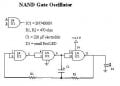
Hi all. I've been trying to make a standard (not CMOS) NAND gate oscillate without success. Can it be done? I can get a CMOS NAND gate IC to work fine using examples posted in other threads, but haven't been able to figure out the non-CMOS gate. All I really want to do is make some LEDs flash. :)

I have a handful of SN74S00N ICs and a few others. Any help would be appreciated.


Thanks in advance,
Doc
 

Ron H

Joined Apr 14, 2005
7,063
I think you can make one oscillate if you use the configuration of Fig. 2 in this app note. What you need to realize is that 74S gates may require as much as 2mA input current in order to get down to the low logic threshold. Therefore, the two resistors need to add up to probably less than about 700 ohms. Start out with R1=470, R2=220, and C=100nF.
A ring oscillator requires an odd number of gates. If you only use 3, it may run faster than you can see on your scope, unless it is fairly wideband.
 

Thread Starter

doggiedoc

Joined Dec 16, 2004
62
Thanks Ron H and beenthere -

I've managed to get it working since I posted the question. It's not a sqarewave like I'd like but at least it's flashing!

Ron the lower resistance values did the trick. I was using RC values from a CMOS oscillator using a 74AC14. The input resistance on that baby is in the mega-ohms.


beenthere - I have some '04s too. I'll try them next.

Here's a schematic of what I did so far. Any pointer's on getting it closer to equilibrium on the oscillations (square wave). It sort of just "blips" now.


Thanks for any input!
Doc
 

hgmjr

Joined Jan 28, 2005
9,027
I would use the spare gate as a buffer between the output of the oscillator and the LED. I would reference the LED to the positive supply with a series current limiting resistor.

hgmjr
 

Thread Starter

doggiedoc

Joined Dec 16, 2004
62
hgmjr - Thank you for your input. I'll just need to figure out what you just said. :p I'm still learning.

I did tie the inputs together and with the lower resistance values it oscillates consistantly now. Before it was somewhat erratic.

By referencing the LED to the positive supply, do you mean a series resistor between the LED and positive instead of negative as I've shown? Oh I also increased the capacitor to 470 uF and it cycles pretty good but still not an equal time on and off.


EDIT: here's an upoad of the correct schematic (so far)
 

Attachments

hgmjr

Joined Jan 28, 2005
9,027
Tie the two inputs of the spare gate together. You can then use it as a buffer. Tie the output at pin 11 to the input of your spare gate and then connect the output of the spare gate to the LED's cathode and then connect a resistor from the LED's anode to the positive supply.

hgmjr
 

Thread Starter

doggiedoc

Joined Dec 16, 2004
62
Thanks! That really works good. I also added a POT in series with R2 to make to flash rate adjustable. What fun!!!

Thank you all for the quick responses.

Now on to that hex inverter. :D
Doc
 

Thread Starter

doggiedoc

Joined Dec 16, 2004
62
Hey! I made a NOR gate oscillator!! :D :D :D

Obviously it wasn't a great leap from the NAND gate version, but I'm pleased with myself!!!
 
Top