 Facebook
 Google
 GitHub
 Linkedin
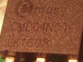
This board is from a harbor freight rechargeable oscillating tool. Advertised oscillating is from 10,000 to 20,000 cycles per second. I need oscillations around 8,000 so I removed the 273( pure experimental here ) resistor and replaced it with a 1k(1/4 watt ) resistor. Oscillations are now adjustable from around 7200 and up. This satisfied my need. I have about two dozen of these I use but one gets hot in hand, quite warm to the touch, and eventually goes to high oscillation. I removed the board and checked resistor(de-soldered) and it was open circuit. I checked diode(1N4007 )(also de-soldered) and it was open circuit. I soldered in new components and results were high oscillation, no adjustment downward. I found data sheet for the mosfet but not the 8 pin IC. I thought maybe some form of 555 timer or op-amp but only guessing. Does anyone know what that chip is? (see picture board3.jpg)
I came up with an idea last night to measure resistance through some of the motors for comparison.
It's always possible I slowed the oscillations below their design criteria!
Oscilloscope shows a nice square wave until motor is soldered in and the wave is very spiky and irregular but still adjustable on all other units.
Bill
Attachments
-
 212.7 KB Views: 23
 -
 217.4 KB Views: 23
 -
 338.1 KB Views: 26
 -
 110.1 KB Views: 24


