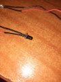
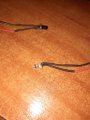
There is only one emitter and one receiver, situated on the corpus(the 3rd and 4th picture from post #15). I think that these two are the IR emitter and receiver. There weren't any part numbers.
The clear one is probably the emitter; the dark red one would be the receiver. The coloration is for filtering ambient light.
I suspect you have a digital camera. The emitter should look like a little white light in the viewfinder. That is, CCD viewfinders are sensitive to IR.
Does it light? If not, that may be the problem. A two wire detector could be a few things. Most are wired to allow or produce an increase in current in the presence of an IR beam from the emitter. Smart detectors (e.g., the ones in your TV remote) show a decrease in signal and are usually 3-wire. The package for that detector does not look like the smart ones I have seen (limited experience, though).
Simply "hot wiring" it may not work. Devices are a lot smarter today than the cars of the 1950's, for example. The controller may look first for a signal showing the latch is working, then for a break in signal upon breaking the beam before activating the UV LEDs.
The controller may look first for a signal showing the latch is working, then for a break in signal upon breaking the beam before activating the UV LEDs.
Then why investigate the IR LED and IR detector (post # 22) if the problem is in the UV boards?
My interpretation to date is that the UV boards light when supplied with an appropriate voltage/current, but when assembled in the device, they do not turn on. To me, that is not a problem with the UV LEDs, but more likely some safety interlock.
Hello guys, sorry for the late replies in the last couple of days, but I've been really busy with studying for my exams. Today was the last one so I expect that I would be able to answer all of your questions faster compared to before. Thanks for all the help that you've been giving me, I really appreciate it . Now, about the lamp, let's assume that we can't find the problem with the board, so I thought of doing something else. Can I remove the board and then connect the cables on the back of the board(labeled LED+ and LED-) to a power supply. Then, when I plug it in, all of the UV LEDs will start emitting light again(at least I think so...). What should I do for that to happen(like what voltage would my power supply be)
I also think that resistor R18 might have gone bad. Its code is 473(which means its 47 ohms), but when I try to get a reading, it stays on 1 and occasionally there is some random number displayed
Re: #27
Yes, you could do that. You could also plug the wall wart (power supply) into a timer. What range of times are used for curing the nails? Given that number of UVLED's I would think it is only a few minutes, but I have never done it.
Re:#28 Code 473 = 47,000 Ω Measure a resistor in circuit is always a problem as you are measuring the whole circuit, not just the resistor.
Edit: Why did you pick R18 to measure? It looks OK to me, but there is a shadow on the left-side solder joint.
Edit2: Glad you are finished with exams. My oldest grandchild just finished his remotely. What a pain in a house full of people. Hope you did well.
About the resistor, it was my mistake. I used a site to convert the codes to ohms and missed the "k". So it would be fine just to desolder LED+ and LED- as well as V- and V+, then solder the two cables together and the boards should light up, right?
Then, when I plug it in, all of the UV LEDs will start emitting light again(at least I think so...). What should I do for that to happen(like what voltage would my power supply be)
Just read post #31
Yes, the boards should light up, but I would not do that without a little more discussion.
Response I was working on at the time:
Well, we really don't know for certain, but you used the supply voltage in the past to check the boards, right? That suggests the voltage is right, but LED's need to have current limiting (i.e., they are "current controlled"). I believe the large mosfet mentioned may be there to modulate (control) the current. The rest of the board is probably for timing and running that modulator.
My advice is to see if we can get the board to turn on. Failing that, if the supply at the LED+/- supply points is controlled/regulated, then your suggestion can should not be done. That would be supplying an unregulated current. If it is not regulated, then you run the risk of a short lifetime for the UV LEDs.
We can come up with some tests to see if the current is regulated (e.g., voltage developed across various resistors).
Edited. Left out a few words for the sake of a timely reply.
Have you given up on the "safety interlock?' Does the clear diode emit IR, as viewed with a digital camera?
To see if it is regulated, I would put various loads across it, say 10, 50, 100, and 200 ohms, and measure the voltage across the resistor. If the current is not regulated, you should read about the same voltage across each resistor. There may be some differences due to loading of the power supply. If it is regulated, the voltages will be different. You don't need all 4 values, but you do want something low and something high but not too high.
At 12V, 10Ω will draw 1.2 A, which will load the supply. It will also produce heat equal to I^2 x R = 14 W. It will get very hot. At 100 Ω, the current will be 0.12A = 1.44 W.
Some comments. In post #13 the voltage measurements on the mosfet pins seem to suggest that it is fully switched on.
In post #15 I think the measured voltage on LED panels of 10.36 volts should be enough to turn the LEDs on. I am working on the assumption that the LEDs are arranged in groups of 3 in series together with a 39 ohm current limiting resistor, I think the large LED panel has 5 groups of 3 in parallel. Each of the smaller panels each have a group of 3 LEDs and a 39 ohm resistor. (I don't understand why there are 6 x 39 ohm resistors on the large panel. I would only expect there to be 5.)
From the pictures in post #1 The power input to the board uses red for positive and black for negative which is what I would expect.
But if you trace the track on the component side of the board it seems to connect to the black wire that goes to the LED panels. to the positive input.
Also the red wire to the LED panels connects to the mosfet drain. Assuming the mosfet is an N channel device I would expect that to be connected to the LED - side. At this point I thought it strange that the black wire to the LEDs seemed to be used as positive to the LEDs. But when I looked at the LED panels the red was connected to the positive marked connection. If the unit had never worked I would have said this was a wiring error but the fact that it had worked really confuses me.
Also the red wire to the LED panels connects to the mosfet drain. Assuming the mosfet is an N channel device I would expect that to be connected to the LED - side.
Les.

 Facebook
 Google
 GitHub
 Linkedin


 . Now, about the lamp, let's assume that we can't find the problem with the board, so I thought of doing something else. Can I remove the board and then connect the cables on the back of the board(labeled LED+ and LED-) to a power supply. Then, when I plug it in, all of the UV LEDs will start emitting light again(at least I think so...). What should I do for that to happen(like what voltage would my power supply be)




