 Facebook
 Google
 GitHub
 Linkedin
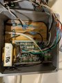
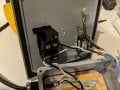
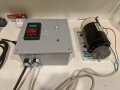
Hi! I finally got all the pieces parts together for my treadmill motor conversion! I'm very pleased. Or maybe I'm just very pleased to be almost done. This is my first project every so i had to do a lot of research. I received good help here on this forum.
What I've got is just a beat old TM motor (more beat than I thought from the pictures on ebay") ) being controlled by an mc-60. I created legs or pigtails or whatever you'd call it from all the connectors on the board so that when I was connecting and disconnecting I wouldn't constantly be pulling on the board. Other than that I have a big fat on off switch, a 5k pot, and a regular 120v light switch wired into the wiper line of the pot. I intent to get a light switch with a little light inside it to indicate when there main power is still on.
) being controlled by an mc-60. I created legs or pigtails or whatever you'd call it from all the connectors on the board so that when I was connecting and disconnecting I wouldn't constantly be pulling on the board. Other than that I have a big fat on off switch, a 5k pot, and a regular 120v light switch wired into the wiper line of the pot. I intent to get a light switch with a little light inside it to indicate when there main power is still on.
My only questions left are
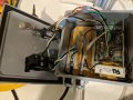
1) I have a ground, of course, coming from the AC. Currently it's just hangin. I don't really know what to do with it.
2) does it look like this thing is going to catch fire after I use it for 15 minutes? I'm thinking, maybe the box is too small, although it feel pretty big.
3) I'm curious as to why people recommend the 5k pot so much. From my research I gather that the difference is the point in which the motor actually engages. I have to turn the pot about 1/4 - 3/8 turn before it starts to move. I'm not going to replace t but I would have rather started with a 10k or 20k which I understand would engage much earlier..
Thanks!
R
What I've got is just a beat old TM motor (more beat than I thought from the pictures on ebay
) being controlled by an mc-60. I created legs or pigtails or whatever you'd call it from all the connectors on the board so that when I was connecting and disconnecting I wouldn't constantly be pulling on the board. Other than that I have a big fat on off switch, a 5k pot, and a regular 120v light switch wired into the wiper line of the pot. I intent to get a light switch with a little light inside it to indicate when there main power is still on.My only questions left are
1) I have a ground, of course, coming from the AC. Currently it's just hangin. I don't really know what to do with it.
2) does it look like this thing is going to catch fire after I use it for 15 minutes? I'm thinking, maybe the box is too small, although it feel pretty big.
3) I'm curious as to why people recommend the 5k pot so much. From my research I gather that the difference is the point in which the motor actually engages. I have to turn the pot about 1/4 - 3/8 turn before it starts to move. I'm not going to replace t but I would have rather started with a 10k or 20k which I understand would engage much earlier..
Thanks!
R
Attachments
-
 4.3 MB Views: 6
 -
 3.8 MB Views: 5
 -
 4.1 MB Views: 5
 -
 4 MB Views: 5


