the Module is in the sch.... connector j6 labelled as supply....
Sorry for Late reply but this is my sixth post/hour which is why i cant post my reply in an hour............ Sorry but this is 1:51AM here so i might sleep hour expires, so see you tomorrow Mr. djsfantasi
Hi all!
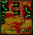
I did some modification in my Schematic and PCB like:
i. Adding decoupling cap of 100u
ii. Relocating the caps positions
iii. adding ground plan on both top and bottom surfaces
Kindly analyze my current design and tell me if there are further corrections or modifications
the current design modifications are shown in the following pics.....
Note: ESP01 footprint can be seen in this design which is absent in my previous one.
Kindly, check the attachment....
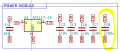
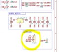
The connector J6 is for the power supply. the power supply takes AC input from and give DC output to the board through this connector. the foot print attached to this connector is also shown in the attached picture; pin 3,4 are the AC Input where pin1,2 are the DC Out.... Kindly tell me if there is any confusion....
Hi sanasana, before you go ahead and make a new board, I would really check with soldering capacitors etc on first with your existing one, as it may not make any difference!!
Kindly, check the attachment....
The connector J6 is for the power supply. the power supply takes AC input from and give DC output to the board through this connector. the foot print attached to this connector is also shown in the attached picture; pin 3,4 are the AC Input where pin1,2 are the DC Out.... Kindly tell me if there is any confusion....
Hi sanasana, before you go ahead and make a new board, I would really check with soldering capacitors etc on first with your existing one, as it may not make any difference!!
yes i can check it by soldering the additional caps but the most imp thing i guess is the ground plane, isnt it? which i think i can get only in a new board?
I cant be 100% certain, as I havent experienced this problem, but my gut feeling is that there must be something pretty bad going on if it is so sensitive to a ground plane.. so if you cant make it work without first, then it might not make any difference.
Ideally the snubber should be matched to the load, but unless your loads are drastically different you could probably find a compromise snubber as a 'one size fits all' solution. Any snubber would be better than none.
Ideally the snubber should be matched to the load, but unless your loads are drastically different you could probably find a compromise snubber as a 'one size fits all' solution. Any snubber would be better than none.
ok Alec but could please share some links so that i could learn about snubber designing.... i mean how to calculate the value of resistor and capacitor and also their power ratings?
Hi,
I have fabricated the the updated designed that i have shared in post#23..... But the issue still exists, however become a bit better like in the old version, the reset occurs on every or at most on the second toggle command while in the new modified version (post#23) , the reset occurs after 4-5 or even more toggle commands....
could anyone please guide me further??
Do you have a DSO where you can set scope to one shot, and look around for
transient ? Trigger on negative edge, set level to - 1V or maybe a little more. To
see where it is worst. Make sure scope probe ground lead short, and connected
to board edge where ground comes into board.
Do the same again for +edge, level set at Vdd+ 1 V.
Board refers to board with UP on it.
For bulk cap are you using a tantalum, preferably a polymer tantalum. You only
have .01 uF ceramics, many designs parallel that with a .1 uF because of high
freq esr considerations. Look at datasheet, not all caps of same value have
equally good esr. .01 take care of highest freqs, .1 next freq range lower, bulk
caps dc and low freq load changes.
Diode clamp on relay, should be a fast diode. Look at with scope to see how
effective it is as a clamp.
What sghioto is suggesting is that the 2n3055 can drive 15 AMPS.
Why do you need such a large transistor to drive a relay? What is the relay part number?
Hi All!
Dana! Thanks for your suggestions, let me evaluate your mentioned point.....
Alec! I havent used any snubber yet.... Kindly you can check my Sch in Post#1.
eetech! the transistor i have used is 2n5551 not the one mentioned in Sch, kindly read post#18
I noticed in your schematic that your 3.3V digital rail is supplied by a "AP1117-15". The AP1117 is a series of fixed or adjustable LDO regulators. The correct part number for the 3.3V fixed version of this part is AP1117x33 (the x refers to the package type). The part number shown, "AP1117-15" looks like, to me, the 1.5V version. Unless your schematic is incorrect, perhaps your digital power supply is too low. The STM8 microcontroller cannot run below 2.95V. Did you measure the voltage on your logic power supply rail voltage?
Thank allan for your observation.
You are right, sch has "AP1117-15" regulator but in real i have used AMS-1117-3.3V, I have checked the power supply voltage to be 3.3v.
 Facebook
 Google
 GitHub
 Linkedin
")