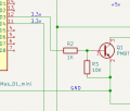
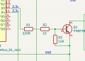
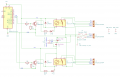
R1 and R2 are used to limit current through LEDs that are part of the optocouplers.
If using optos, put those back where they were. 1k is good enough for the base. adding 220 Ohm will not change anything there
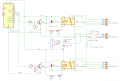
Final schematic:
1) Removed LTV-356T Opto.
2) Added 10k between Base and Emitter of the PMBT3904.
3) Connected LED to 5v line instead of the collector line on the PMBT3904.
4) Replaced 200R with 220R.
5) Replaced normal fuses for blade fuse holders.
6) Replaced 18v G5LE-1 relay with the correct 5v relay G5LE-1A4 DC5 model.
7) Added a solder pad for the always on (AO) +12v line.
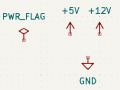
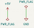
Every pin that is deemed a power input, requires a source identified by a power flag, the exception is usually any device that supplies it with its relevant pin, identified as power out.
As in a 3pin regulator IC for example, 7805 etc.

 Facebook
 Google
 GitHub
 Linkedin