My Custom PIC Board

Thread Starter

MTech1

Joined Feb 15, 2023
181
Hello,

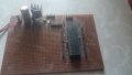
I known many people just use ready-made board for programming, but I created my own development board from scratch by soldering components onto a circuit board. This is helping me learn more about hardware interfacing.

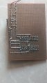
I drew a diagram to show all the connections. So far, everything is working fine up to the point where the green LED is working.

However, I'm having trouble with the connection between the ICSP connector and the Microcontroller PIC18F45K22. I'm not sure if the connection is correct on the board. I don't want to damage anything

If you have experience with ICSP connections or programming the Microcontroller PIC18F45K22, I'd really appreciate your help. I've attached the diagram to show the connections. I'd like to discuss this in more detail and hopefully find a solution.

1699091743235.png
 

Attachments

Last edited:

Thread Starter

MTech1

Joined Feb 15, 2023
181
I've completed all the connections on the PCB board, but I'd like to ensure that everything is correctly connected.

If anyone could take a look at the bottom of the board and confirm that the connections are accurate for ICSP , it would greatly ease my concerns. Your validation would be valuable to me.
 

Jon Chandler

Joined Jun 12, 2008
1,595
It's impossible to determine exactly what you've got on your board, but as Bob pointed out, you need a 10k pullup resistor between /MCLR and +5V. Your schematic shows a series resistor between pin 1 of the PIC (/MCLR) and the /MCLR pin on the 5 pin header, which is wrong. I think this is what you have on your board too but like I said, I'm not certain.

So pin 1 of the chip should be connected directly to pin 1 of the ICSP header, and a 10k resistor connected between there and +5V.
 

Thread Starter

MTech1

Joined Feb 15, 2023
181
It's impossible to determine exactly what you've got on your board,

So pin 1 of the chip should be connected directly to pin 1 of the ICSP header, and a 10k resistor connected between there and +5V.
I have marked 10 K resistor with red line. M represent MCLR pin. G represent Ground. V represent VDD.

IMG-20231104-WA0007.jpg
 

hexreader

Joined Apr 16, 2011
619
Looks correct to my eye

I see no problem with R3 and MCLR

If it were my board, I would unplug the PIC and check for shorts between tracks using a multi-meter on resistance range.

One track in particular looks iffy. Pin 1 looks like it may be shorted to GND (centre left in the attached picture)

Screenshot 2023-11-04 141853.png
 

nsaspook

Joined Aug 27, 2009
16,318
Put a 0.1uf bypass between pins 32 31 like are on pins 11 12. Never trust internal chip vdd vss power wire routing for bypass cap requirements on each controller power pin.
 

Thread Starter

MTech1

Joined Feb 15, 2023
181
If it were my board, I would unplug the PIC and check for shorts between tracks using a multi-meter on resistance range.

One track in particular looks iffy. Pin 1 looks like it may be shorted to GND (centre left in the attached picture)
Thank you for your suggestion. I already done unplugged the PIC from the socket. After conducting a continuity test, measuring voltage, I found no issues. I agree that the connection between pin 1 and ground may be short. I posted to get the advice if I am missing anything for a more experienced person

I appreciate your input in helping me troubleshoot the board.
 

Thread Starter

MTech1

Joined Feb 15, 2023
181
Put a 0.1uf bypass between pins 32 31 like are on pins 11 12. Never trust internal chip vdd vss power wire routing for bypass cap requirements on each controller power pin.
I have already added 0.1uf across pin32 31. Look at top view of board and connection diagram. You can see there are two ceramic capacitors
 

nsaspook

Joined Aug 27, 2009
16,318
I have already added 0.1uf across pin32 31. Look at top view of board and connection diagram. You can see there are two ceramic capacitors
Ok, your drawing (that demonstrates why schematic drawing programs are necessary) looks like a 1uf power cap on pins 32 31 that should be there too. I usually pair a 0.1uf and 1 to 10uf cap on all power pins for bypass and power filter on these types of boards or at least use solid wire jumpers to share power on the pin with two bypass caps and one power filter cap. You've done an excellent job with that board compared to my hack-job vector-board.
https://forum.allaboutcircuits.com/threads/help-with-the-pic18f45k22.193545/post-1819187
1699114945920.png1699114969326.png
 
Last edited:

Thread Starter

MTech1

Joined Feb 15, 2023
181
I removed the pic from the socket and powered board 12V DC . I measured 5 V across the supply and ground rail. I also measured 5 volts across pin 11 and pin 12, and 5 volts across pin 31 and 32. Finally, I measured 5 volts across the VDD and ground of the ICSP connector.
 

nsaspook

Joined Aug 27, 2009
16,318
I removed the pic from the socket and powered board 12V DC . I measured 5 V across the supply and ground rail. I also measured 5 volts across pin 11 and pin 12, and 5 volts across pin 31 and 32. Finally, I measured 5 volts across the VDD and ground of the ICSP connector.
Time for the moment of truth smoke test?
 

nsaspook

Joined Aug 27, 2009
16,318
I believe it's the right moment to apply power and verify if everything is working as expected. Could you please explain what the 'smoke test' involves?
The (magic) smoke is a signal. No smoke good, little smoke bad, lots of smoke very bad.
 

Thread Starter

MTech1

Joined Feb 15, 2023
181
I've connected the PicKit 3 to the board and supplied a 12-volt DC input power, but I'm getting an "Invalid Device ID" error that says, "Target device ID is invalid. Please check your connection to the target device."

https://microchipdeveloper.com/dtda... list of,or an unstable mechanical connection.

I've done some research, and it seems this issue might be related to a faulty connection on board. I've connected the PicKit 3 according to the connection diagram, i measured 5V across VDD and GND of ICSP but I'm not sure where the problem lies.

Anyone can help how to troubleshoot this issue step by step.
 

hexreader

Joined Apr 16, 2011
619
Random things that come to mind:

1) Make sure that the wires from PICkit3 (PK3) to your board are short. 30cm maximum, 10cm or less for perfection.
If you do it carefully, you can plug PICkit3 directly into the board. Take care not to put any strain on the PK3, as it's weight may bend your board pins.
Make sure that PK3 pin 1 aligns with header pin 1 (MCLR). PK3 pin 6 should be hanging off of the end of your ICSP header, unconnected

2) With PIC inserted, check for continuity from ICSP header pin 1 to PIC pin 1. put your probe on the actual PIC leg to prove good socket connection. Repeat for the other 4 ICSP header pins

3) Check for shorts between ICSP header - pin 1 to pins 2,3,4,5 - pin 2 to 3,4,5 - etc. With PIC inserted expect some continuity between pins, but I would declare anything less than 10 ohms as a short, even with PIC inserted.

4) check all 5 ICSP pins for short to ground and short to +5V

5) check PIC pins 1,39,40 for short to adjacent pins on PIC and for short to +5V and ground

6) remove PIC and check for partial shorts to adjacent PIC pins, to +5V and to ground. Pin 1 will show 10K to +5V, all other pins should show overload on all multi-meter resistance ranges
 

Thread Starter

MTech1

Joined Feb 15, 2023
181
That would explain it...

Post number 6 shows the likely location of the short to ground
I'm a bit confused because the one joint of PIC pin 1 and resistor end should connected to ground, which is why I connected it to the ground rail. Could you please advise on how to rectify this connection?
 
Top