 Facebook
 Google
 GitHub
 Linkedin
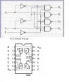
Recently I downloaded a data sheet, which gave pin lay out as given in attachment. I want to connect four NAND gates to get 2 to 4 decoder.I wish to connect, on breadboard, the four NAND gates to get the decoder. I notice in pin lay out Vss at pin 7 and Vdd at pin 14. I wish to use Arduino board to power and experiment. I got following questions:
1.Do I connect 5V Arduino pin to pin 7 of IC?
2.What do I connect to Vdd? GND?
3. Can I connect the circuit without using E part in the figure?( file attached)
I have written a sketch to get physical verification of the decoder using leds but can't try out unless I get the circuit right.
Needless to say it just for experimentation.
I have attached a file which gives two pictures- one for constructing decoder and another the pin layout.
I would be thankful o those who would spend ime to answer my elementary questions.
sureshparanjape
Attachments
-
 34.8 KB Views: 71
")


