Facebook
 Google
 GitHub
 Linkedin
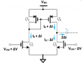
I am studying these diagrams:

I don't understand why on the figure (c) above, the current through Q2 flows upwards. This is NMOS transistor and the current should flow from its drain towards the source. If as in this case, we have a negative voltage applied to its gate, the I would expect the current flow to be limited (limited because this is small signal analysis, normally for DC I would expect a cut off), and therefore a larger current through Q1. So in other words Id of Q2 should flow downwards with a magnitude lower than Id of Q1. Why it is not the case?
I don't understand why on the figure (c) above, the current through Q2 flows upwards. This is NMOS transistor and the current should flow from its drain towards the source. If as in this case, we have a negative voltage applied to its gate, the I would expect the current flow to be limited (limited because this is small signal analysis, normally for DC I would expect a cut off), and therefore a larger current through Q1. So in other words Id of Q2 should flow downwards with a magnitude lower than Id of Q1. Why it is not the case?