Multistage preamp . Some suggestion for improve it.

Thread Starter

DaniKowa

Joined Sep 23, 2020
218
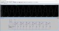
Hello everyone, I created this pattern based on other patterns found elsewhere. Unfortunately, it doesn't work as I would like, and I explain why. The initial idea was to create a multi-stage circuit where each stage guaranteed a fixed gain, but this does not happen since when I join the next stage I lose gain in the previous stage. Another problem is the loss of phase linearity. For example, between the input point IN and the output of the first stage A1, I have a drift of -33 ° at 10Mhz. This I would like to avoid even at the cost of changing components as it is an old JFet that can be good for guitars but probably not for this purpose. I have tried other Fet, but the drift problem occurs in an accentuated way in all of them. Maybe I haven't found the right component, or it doesn't exist. The number of stages is theoretically unlimited, this is to say that I would not worry about having 10-15 stages with low gain and high phase linearity if the conditions I will write below are present. So the request for help (if possible) concerns:
1) Gain stabilization (even less than 10 if necessary to limit phase drift) on each stage so that each stage offers and maintains a stable gain at the next stage.
2) limit as much as possible the phase drift described above.

Thank you in advance.
 

Attachments

Audioguru again

Joined Oct 21, 2019
6,692
Since the output resistors have the extremely high value of 1 Meg ohms then a tiny capacitance caused by the way it is wired will affect gain and phase at the high frequency of 10 MHz. A solderless breadboard will cause disaster.

If the 1Meg output resistors are 18k ohms then it will be much better, but the gain will be a little less.
The 100nF output capacitors feeding the 1 Meg output resistors have an earthquake cutoff frequency of 1.6Hz.
If you use 18k output resistors then the 100nF capacitors must be 5.6uF to have a cutoff at 1.6Hz.
 

Thread Starter

DaniKowa

Joined Sep 23, 2020
218
Good evening,

I can find some time after dinner to read your posts, and I started doing some tests. Keep in mind that my training is technical but not specific in electronics, so it justifies any errors even repeated. I use this simulator on different computers depending on where I am, and a strange thing is happening to me. I have the same version and the same database but different computers and opening and simulating the same circuit I have completely different results. Furthermore, I am attaching the two screenshots of the two different computers. I think the one on FX is more reliable, but I am waiting for your comment. Who is right between the two? Thanks.
 

Attachments

Audioguru again

Joined Oct 21, 2019
6,692
An MPF102 Jfet has a wide range of specs. Some are much more sensitive than others. A simulation shows only one device and guesses about its sensitivity.

If you build the circuit some will be more sensitive than others.
An opamp uses negative feedback so that the sensitivity of a circuit is the same even if the opamps have minimum or maximum specs.
 

Thread Starter

DaniKowa

Joined Sep 23, 2020
218
OK but this do not explain why with same database and circuit I've different simulation behavior of the circuit. Probably there something different on database. I will check again tomorrow.
 

crutschow

Joined Mar 14, 2008
34,452
I am attaching the two screenshots of the two different computers. I think the one on FX is more reliable, but I am waiting for your comment. Who is right between the two?
If the simulation parameters and models are exactly the same, then I can see no reason for the difference.
The computer used for the simulation should have no effect on the results.
 

Audioguru again

Joined Oct 21, 2019
6,692
What is the purpose of such a simple cascaded circuit that operates at an FM radio station frequency and has nothing to control the gain or attenuate an overloaded input?
 

Thread Starter

DaniKowa

Joined Sep 23, 2020
218
In this case I want to understand how they work and study their possible uses. I entered 100Mhz to see how far these components are out of phase which would be different to 1 or 10Mhz.
 

Audioguru again

Joined Oct 21, 2019
6,692
Did you know that the antique MPF102 is obsolete and is not made anymore?
Did you buy fake ones from ebay?
If you find some real ones then each will have slightly different specs and will work differently from the others, including simulations.
 

DickCappels

Joined Aug 21, 2008
10,180
I have some MPF102's but I stopped using them 20 years ago because of the wide variation in parameters, particularly VGss, made it too much trouble to use.
 

Thread Starter

DaniKowa

Joined Sep 23, 2020
218
The reason I've used them is the large amount of schematic found to use on LTspice. Today there are diverse devices better than 102. In fact I could also use another jfet for the analysis which would probably get better results. The problem is which one! .
 

Thread Starter

DaniKowa

Joined Sep 23, 2020
218
Surely in 20 years the components will be better and more reliable. I ask again if anyone will want to answer. Even new components I always see the phase loss present. In this case the image represents a first stage of a jfet cascade. This graph represents a more recent J202 but still has a phase shift of approximately 50 ° when connected to the next stage while it reduces to 15 ° in single stage. The question is is there any way to limit this phase loss when it is cascaded? Thank you again.
 

Attachments

Audioguru again

Joined Oct 21, 2019
6,692
Of course there is more phase loss when one stage drives the input capacitance of the next stage. The loss will be less in a simulation that is missing the stray capacitance of wiring and the simulation never has "maximum" device capacitance..
 
Top