Multiple mode inputs

Thread Starter

STech2106

Joined Jul 8, 2023
43
Hi guys,

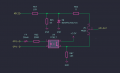
I have inputs from a microcontroller that can be configured as either digital or analog inputs. I would like to protect them from direct 12V voltages. The controller operates at 3.3V. I had thought of using an opto-isolator, but by doing so I would no longer have the option of reading the analog signals.
Has anyone had the same need as me?
It would be nice to be able to use one terminal and switch between the two modes with a jumper....

Does anyone have any ideas?
 

meth

Joined May 21, 2016
298
There are more sophisticated ways to do it, using transistors or op amps (or opto coupler as you mentioned), but just to protect it from voltages over 3.3V you could probably put a zener diode between the input and the GND?
 

Thread Starter

STech2106

Joined Jul 8, 2023
43
Yes, I could do that, but I would prefer the two circuits to be separate, even if only when acquiring a digital signal. A zener diode, near its conduction, would affect the analog measurement.
 

MisterBill2

Joined Jan 23, 2018
27,186
Consider that diode clamping is a common and effective scheme for both analog and digital ports, although recently I have been reminded that the voltage supply connection also needs to be protected. THAT can be achieved with series resistors and zener diodes.
 
Last edited:

Thread Starter

STech2106

Joined Jul 8, 2023
43
Hi guys,
@MisterBill2 @MrChips @crutschow

Sorry for my delay.

I took tried to put your advice into action and designed the attached circuit.
Does it make any sense in your opinion?

My goal is to have an opto-isolated input , but also maintain the capability of using the internal ADC when optoisolated mode is off.

circuit mode.png
 
Last edited:

Ian0

Joined Aug 7, 2020
13,097
I'd simplify it.
Delete the switches.
Connect the opto transistor so that the collector is at 3.3V and the emitter connected to the input, with a 10k pull-down resistor.
If the opto-isolated input is not being use, the transistor will be off, and you can connect the analogue input either straight to the input, or via a divider, and the 10k resistor forms one half of the divider.
I would not recommend the use of D19. If there is an over-voltage on the input, then current will flow into the 3.3V power supply and may raise the voltage by enough to damage the microcontroller.
 

Thread Starter

STech2106

Joined Jul 8, 2023
43
Thank you for the advice. Maybe I confused the drawing. ADC1 is not a terminal it is just a label. That is why I had to introduce a switch
 

Ian0

Joined Aug 7, 2020
13,097
Thank you for the advice. Maybe I confused the drawing. ADC1 is not a terminal it is just a label. That is why I had to introduce a switch
I would suggest that you have extra terminals instead of the switch. I think it would eliminate misconnection, or having the switch in the wrong position for the inputs that have been connected.
 

Thread Starter

STech2106

Joined Jul 8, 2023
43
Hi @Ian0,

I have modified everything according to your suggestions.
However, I have a question. If I connect a signal to the opto-isolated input, I would have voltage on the ADC1 connector.
What do you think about the configuration in the image below with two jumpers?
 

Attachments

Ian0

Joined Aug 7, 2020
13,097
Hi @Ian0,

I have modified everything according to your suggestions.
However, I have a question. If I connect a signal to the opto-isolated input, I would have voltage on the ADC1 connector.
What do you think about the configuration in the image below with two jumpers?
Yes. That's good.
3.6V zeners are not good zeners. They will probably start conducting well before the input gets to 3.3V and will mess up the divider.
Are your ADC inputs 5V-tolerant? If so use a 5.1V zener which will have a much sharper curve.
This is another way to clamp the input. It doesn't completely eliminate current into the supply, but it reduces it by a factor of Hfe.
If the fault current into the supply is lower than the load current on the supply it does no harm.Screenshot from 2025-05-24 20-26-01.png
 

Thread Starter

STech2106

Joined Jul 8, 2023
43
Yes. That's good.
3.6V zeners are not good zeners. They will probably start conducting well before the input gets to 3.3V and will mess up the divider.
Are your ADC inputs 5V-tolerant? If so use a 5.1V zener which will have a much sharper curve.
This is another way to clamp the input. It doesn't completely eliminate current into the supply, but it reduces it by a factor of Hfe.
If the fault current into the supply is lower than the load current on the supply it does no harm.View attachment 349847
No, my inputs do not tolerate 5v, they only work at 3.3v
 

Ian0

Joined Aug 7, 2020
13,097
That's a shame. Either use the transistor clamp, or try this one.

Screenshot from 2025-05-24 20-51-31.pngV1 is some higher voltage supply you might happen to have. 5V or 12V etc. Select R1 to give the rated current for the zener. That way you might stand a fighting chance that it might bias up pretty close to 3.3V.
 
Top