multiple component break out board

Thread Starter

jgerardi

Joined Jul 21, 2024
3
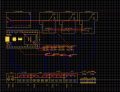
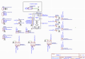
I am working on a pool control using an esp32u, a couple of relays and a 120v to 5v power supply. I find that dependable hardware and connections are the hardest thing to deal with.
I was wondering how i would go about having a pcb made up has pin connectors for the ESP32u module and pin connectors for the power supply and relays.
Any thoughts on how i could do something like this?
 

LowQCab

Joined Nov 6, 2012
5,101
I would use only SSRs, ( Solid-State-Relays ), for controlling other Factory-Installed-Power-Relays,
and put all other electronics INSIDE the house, far away from moisture and Corrosive-Pool-Chemical-Fumes.

At least install all of the Electronics in a completely-separate, completely-sealed, Plastic-Box.
.
.
.
 

samunal

Joined Jul 3, 2024
26
Yes you can go for a custom PCB to do that, That type of things are knows as shields. Where you can plug your all the electronics and modules. Then for relays you need a separate PCB to hook them into the motherboard(shield). I think that's a grat idea for prototype but not for actual product. But you can design this thing seamlessly in any online pcb designer I would reccomend to use EasyEDA and JLCPCB intergrated work enviorment for this. If you can go with SSR that would be great but complex design and a lot of limitations with high power, see I have designed one SSR project here on my hackster profile:
 
Last edited by a moderator:

Thread Starter

jgerardi

Joined Jul 21, 2024
3
Yes you can go for a custom PCB to do that, That type of things are knows as shields. Where you can plug your all the electronics and modules. Then for relays you need a separate PCB to hook them into the motherboard(shield). I think that's a grat idea for prototype but not for actual product. But you can design this thing seamlessly in any online pcb designer I would reccomend to use EasyEDA and JLCPCB intergrated work enviorment for this. If you can go with SSR that would be great but complex design and a lot of limitations with high power, see I have designed one SSR project here on my hackster profile:
Thanks. I generally managed to figure out the EasyEDA program but i have lots of learning to do. I made a very rough PCB but im not sure how to get the correct female headers that i would need to plug the ESP32 u into.
See attached files
 

Attachments

MaxHeadRoom

Joined Jul 18, 2013
30,562
In the rest of the world, "shields" are conductive and used to block radiated energy fields.
There are currently two definitions One is EMI Cable shielding, the other such as Arduino shields which are boards that can be plugged into a Arduino PCB in order to extend its capabilities. these shields allow you to control Arduino projects with your phone, with a blue tooth or even a touch screen to add a visual component.
 

ronsimpson

Joined Oct 7, 2019
4,648
In the layout you never allow Line and Neutral to get near digital lines. You have L and N passing in between pins on the computer. I try to keep 7mm clearance around the L and N. Here I put the "Light" connector next to the contact part of the relay. Connect up the traces with thicker traces.

I would draw a line, left to right, down through the relays. Contacts and connectors above the line and 5V things below. The power supply is the same. 120V above the line and 12V/5V below the line.
1723918752140.png
 

MisterBill2

Joined Jan 23, 2018
27,186
Certainly "R" makes a very good point. Aside from creating a probable shock hazard and importing noise to the digital portions of the design, if leakage develops there is the probability of rather serious destruction of sensitive components.
There are published rules as far as distances between mains voltages and logic voltages, as well.
 
Top