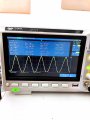
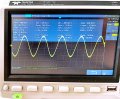
Could you post the waveform, so that I can estimate just how clipped it is.
If the frequency is wrong, it should make no difference, so either:
The reference signal at the op amp non-inverting input is too large
The feedback capacitor is too small
The capacitor being measured is quite a lot larger than you think it is
or
the voltage on what you think is ground (on your incoming connector) has some signal on it.
The reason I asked about the dielectric is that NPO is accurate and others (R7F for instance) can have very wide tolerances.
Could you post the waveform, so that I can estimate just how clipped it is.
If the frequency is wrong, it should make no difference, so either:
The reference signal at the op amp non-inverting input is too large
The feedback capacitor is too small
The capacitor being measured is quite a lot larger than you think it is
or
the voltage on what you think is ground (on your incoming connector) has some signal on it.
The reason I asked about the dielectric is that NPO is accurate and others (R7F for instance) can have very wide tolerances.
Hi, i am attaching two pictures, the one with smaller output peak-peak has lower gain and it is of the channel positioned in the first column- first row. The picture with higher output peak-peak has greater gain and it is positioned in the first column-third row. I am giving in input a sinusoidal wave of 650 mV peak-peak and 35kHz
Hi, i am attaching two pictures, the one with smaller output peak-peak has lower gain and it is of the channel positioned in the first column- first row. The picture with higher output peak-peak has greater gain and it is positioned in the first column-third row. I am giving in input a sinusoidal wave of 650 mV peak-peak and 35kHz
Your "sinewaves" have obvious distortion. What is the part number of the opamps that might work poorly at 35kHz?
Please post a schematic of your circuit.
Your "sinewaves" have obvious distortion. What is the part number of the opamps that might work poorly at 35kHz?
Please post a schematic of your circuit.
I am using ADA4610-4, this is the schematic of a single channel. In total I am using 12 ADA4610-4, in which I use 2 opamps as amplifiers for two channels and the remaining two as buffers.
I mean that your virtual ground at the inputs to the opamp needs an actual DC path to ground. Capacitor C1 prevents that from happening and the signal source V1 prevents that as well. You might have missed that detail at some point.
A DC path is one that does not have frequency dependent components like inductors and capacitors in the way.
I’ll have to disagree with you there. The non-inverting input comes from a signal generator which must be DC coupled, otherwise the average DC level would be floating all over the place.
The inverting input has a DC path via the 10M resistor to the output. Without the capacitors it would be a unity-gain follower.
My suggestion would be to replace the 1nF||10MΩ combination with a 4.7k resistor, which has about the same impedance at 35kHz. It will mess up the phase, but it appears that only the amplitude of the output is of interest. In its present state, the op-amp is driving a capacitive load (1nF and 9nF in series) which normally doesn’t bode well (bad pun, sorry!)
I mean that your virtual ground at the inputs to the opamp needs an actual DC path to ground. Capacitor C1 prevents that from happening and the signal source V1 prevents that as well. You might have missed that detail at some point.
A DC path is one that does not have frequency dependent components like inductors and capacitors in the way.
so if I am getting it right, you are suggesting to add a discharging capacitor from the supply to ground, right? It is already represent in the PCB board I am testing
so if I am getting it right, you are suggesting to add a discharging capacitor from the supply to ground, right? It is already represent in the PCB board I am testing
NO! That is not what I am suggesting at all. Both of the inputs to an opamp are supposed to be at the same potential. Onoe of them is normally connected by a resistor so that the output can compensate for the difference between the inputs. The other input needs to establish a DC path to ground for the bias currents to flow and to establish a DC operating point in the absence of any input.
This should be "Opamps 101" and I'm having difficulty trying to express the concept in terms that you can grasp. It is true that there is some disagreement from another member, but I'm not sure what he has in mind as an alternative. If you don't like my answer, ask him to explain it.

 Facebook
 Google
 GitHub
 Linkedin