Multi-touch Plates Circuit 555 Timer

Thread Starter

hazim

Joined Jan 3, 2008
435
Hi all.

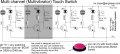
I have the following tableau or whatever is called in my CCTV store. This tableau has 4 shutters that I open to connect a certain camera with power DC connector and BNC cable that is connected to a screen, for customers to view the camera's image.


What I need to do is: A switch beside each camera, if the switch is pressed the corresponding camera will be connected to the screen, if another switch is pressed, the first camera (or the rest cameras) will be disconnected and the camera that's connected to the switch will be connected to the screen.

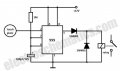
The switches are preferred to be touch plates, I would use stainless plates. The below 555 timer touch circuit is ideal for one camera, the relay connect the video wire when the plate is touched, and it will disconnect after about 100 seconds.


The problems now is to make 20 similar circuits for the 20 analog type cameras at the right, and connect all together so if a certain plate is touched the screen will switch to the corresponding camera.

The relays of each circuit will be connected to a common line, to the screen, and the other pin (N.O) are connected to the cameras. When a plate is touched, the relay switches ON and connects the camera to the screen, this is simple, but this should also disconnected the other cameras (i.e switch OFF any other relay). I thought about connecting the output of the 555 timer of the circuit of the camera that is to be turned ON, to a transistor that discharge the capacitors of the other circuits, but this will make it unable to switch ON another camera as the capacitor of this latest camera and any other camera is being shorted by the transistor. Here is my problem.

Any idea is strongly appreciated.

Regards,
Hazim
 

Attachments

ronv

Joined Nov 12, 2008
3,770
I'm trying to think of an easy way to do it, but cannot.
One way would be to add a short timer (say another 555) in front of the current one and use it to trigger the original timer.
Then you could use any long timer firing to reset all the others.
A gate would be needed for each timer to block the reset if the short timer for that circuit was timing out.
There are some holes in this logic, but not big ones. :D
 

Reloadron

Joined Jan 15, 2015
7,515
Have you given any thought to an analog multiplexer / demultiplexer type design? Just place a On/Off power switch beside each camera and then mux the video to a single channel to the monitor. Use a rotary or thumb wheel switch the channels in bcd format to the mux. A pair of 16 channel mux chips would give you 32 channels allowing 1 of 32 to the camera. Maybe something like that? I never built one but it seems logical.

Ron
 
Last edited:

AnalogKid

Joined Aug 1, 2013
11,037
Maxim has some outstanding video mux chips for an all electronic switching system. But first...

What is the reason for the 100 second timeout? Things would be easier if you just left the monitor connected to the last camera selected no matter now long ago it was. But it is a minor inconvenience for the circuit.

You need to separate the selection function from the timeout and/or reset function. There are many auto-bailing circuits from the 50's with neon bulbs and the 60's with SCR's, but we have other ways now that were ridiculously expensive then. The design task is similar to one of the game controller treads of last year, where a circuit selects who pressed a button first and locks out all others for a timed or resettable period. This task is easier because only one button is being pressed at a time.

I'm sure this can be done with a PIC scanning a switch array and sending an output command to some SPI bus relay drivers, but where's the fun in that? Try this:

40 cameras, so 40 switches each with a pullup resistor. Each switch line goes to one input of a either 5 octal latches or 10 quad latches that have a common clock input. Either way, you need 40 latches, one per switch. Each individual latch output goes to a driver transistor and a relay. The 5 or 10 clock lines for the latches are tied together as a single latch signal. You can derive the latch signal from the buttons by tying together a bunch of OR gates, but doing a wire-or all of the inputs to the base of a single transistor is a lot less work. Any time anyone presses any button, all latches are clocked and capture the status of all 40 inputs. Unlike a game circuit there is no lockout; if you hold one switch while pressing another, both will be latched.

So you've got 5 or 10 latch chips instead of 40 555's, and no timers. If you still want the automatic shutoff after 100 seconds, the latch chips must have a common reset input. The common latch signal can fire a 555 to generate a reset pulse for the common reset signal.

A slightly more complex method is to use priority encoder chips to combine the 40 inputs to a 6 bit binary number, latch that as before, and use the binary signals to drive the address inputs of an array of three 16-input video mux chips. Same overall result, no relays. Actually, that sounds like a nice little project.

ak
 

Thread Starter

hazim

Joined Jan 3, 2008
435
40 cameras, so 40 switches each with a pullup resistor. Each switch line goes to one input of a either 5 octal latches or 10 quad latches that have a common clock input. Either way, you need 40 latches, one per switch. Each individual latch output goes to a driver transistor and a relay. The 5 or 10 clock lines for the latches are tied together as a single latch signal. You can derive the latch signal from the buttons by tying together a bunch of OR gates, but doing a wire-or all of the inputs to the base of a single transistor is a lot less work. Any time anyone presses any button, all latches are clocked and capture the status of all 40 inputs. Unlike a game circuit there is no lockout; if you hold one switch while pressing another, both will be latched.
I need to do this for the 20 cameras on the right only, and another circuit board for 5 or 10 cameras on the other side, as they are different types and each set is connected to a different place.

Anyway I think what you say in the quote is the best one. I need to add the touch switch circuit for each camera.

Regards,
Hazim
 
Hi, i just designed a simple switching circuit using multivibrate system, most probably this circuit may help you., but i just designed, but not yet made this circuit.,
you can give me the feedback if it is success.
Best regards.
Ziyan A. Hameed
Sri Lanka. ziyan a hameed.jpg
 
Hi,
after i have uploaded the above Circuit, i have been thinking more about this, and then made some
changes on the above circuits, therefore i hope the second circuit will be more accurate for your demand.
cost of the spare parts for each unit in Sri Lanka is nearly 40 Rupees (Nearly 33 US pennies)
Best regards.
 

Attachments

Last edited:

blocco a spirale

Joined Jun 18, 2008
1,546
Consider using SR flip-flops (one per camera); when any latch is Set it sends a Reset pulse from its output, via a capacitor and steering diodes, to all to other flip-flops. This would not entirely negate the possibility that more than one output latch could be set simultaneously but it is easy to connect the relay contacts in a hardwired priority scheme so that only one camera can be connected to the output at any time.

In fact, if you can live without touch-plates, you could implement the whole thing using latching push-button switches and change-over relays.... or no relays at all, just change-over latching switches..

Relay Priority.png

There may be a risk of crosstalk with all those disconnected video outputs coupling into the output so I would also add a power switch to each camera and only enable the cameras being compared.
 
Last edited:
hi
thanks for your question.,
the second circuit is mostly suitable for Mr. Hazim's Request. the circuit works as follows:-
you may know simple Multivibrator circuits made with 2 Transistors, 4 resistors, 2 capacitors and 2 LEDs.
if you can understand the function of that circuit, you may also able to understand my switching circuit.
i attache here the experimenting LED Multivibrator circuit first.

in the above circuit, the +ve voltage comes throe the 22k resistor, and it goes to the Base of first Transistor, with that base voltage, the transistor starts to work, and it make a connection emitter with collector, therefore the collector gets a negative voltage, that negative voltage passes throe the 47 ohms resistor to the First LED, at the same time the first capacitor takes the voltage - at this charging time the Switching Transistor goes off and the secont ransistor starts to work same like the first one, and then it also works same lime the first Transistor, therefore it works as a multivibrator one after another., this is the most popular circuit in Electronic Industry. even for my switching circuit just i have made a small changes for this circuit. (but the valuve of Resistor i have given differently in both circuit - it because of the Switching circuit may get the power supply of 6 or 12V, but the LED circuit works with 3V), by increasing the valuve of capacitor as 220 or 470 or as 1000 micro-farad you can make the time of blinking LED as delay, and also by reducing the value of capacitors such as 47 or 22 or 10 micro-farad you can make the speed of Blinking LED more faster.
anyway this 2 transistor Circuit Multivibrator LED works one after another continuously. but in the switching circuit what i have given it works only when touch the touch plate., if you are just trying first time, better make with 2 or 3 transistors and get experience. - LED Multivibrator.jpg Ziyan A. Hameed multi channel Switch 2.jpg
when you making the Relay Switching circuit, you can make it without relay and check the result by the LED, if that is success, you can install the relay.
Note:---- if anyone may need on or off more than one at a time, this circuit is not suitable, it because of this is a multivibrator circuit circuit.. when pressed one button - the previously worked Switch goes off.
 
Last edited:

blocco a spirale

Joined Jun 18, 2008
1,546
hi
thanks for your question.,
the second circuit is mostly suitable for Mr. Hazim's Request. the circuit works as follows:-
you may know simple Multivibrator circuits made with 2 Transistors, 4 resistors, 2 capacitors and 2 LEDs.
if you can understand the function of that circuit, you may also able to understand my switching circuit.
i attache here the experimenting LED Multivibrator circuit first.

in the above circuit, the +ve voltage comes throe the 22k resistor, and it goes to the Base of first Transistor, with that base voltage, the transistor starts to work, and it make a connection emitter with collector, therefore the collector gets a negative voltage, that negative voltage passes throe the 47 ohms resistor to the First LED, at the same time the first capacitor takes the voltage - at this charging time the Switching Transistor goes off and the secont ransistor starts to work same like the first one, and then it also works same lime the first Transistor, therefore it works as a multivibrator one after another., this is the most popular circuit in Electronic Industry. even for my switching circuit just i have made a small changes for this circuit. (but the valuve of Resistor i have given differently in both circuit - it because of the Switching circuit may get the power supply of 6 or 12V, but the LED circuit works with 3V), by increasing the valuve of capacitor as 220 or 470 or as 1000 micro-farad you can make the time of blinking LED as delay, and also by reducing the value of capacitors such as 47 or 22 or 10 micro-farad you can make the speed of Blinking LED more faster.
anyway this 2 transistor Circuit Multivibrator LED works one after another continuously. but in the switching circuit what i have given it works only when touch the touch plate., if you are just trying first time, better make with 2 or 3 transistors and get experience. - View attachment 83023 View attachment 83024
when you making the Relay Switching circuit, you can make it without relay and check the result by the LED, if that is success, you can install the relay.
Note:---- if anyone may need on or off more than one at a time, this circuit is not suitable, it because of this is a multivibrator circuit circuit.. when pressed one button - the previously worked Switch goes off.
The two-transistor astable multivibrator is a well known and understood circuit, but that's not what you've drawn in #7.

Imagine that you touch the grey contacts and the grey transistor switches on, when you remove your finger, how is that base current maintained? Regardless of what happens elsewhere in the circuit, it can't receive any DC base current to hold it on because it's AC coupled via the capacitor; so how does it latch on?
 
Last edited:
i think you have confused and also making me confuse, just try to make it without more creating doubt,
i have not sent 7 circuit, and also there is no 7 circuits in this. some people acts same like they know everything, but not helps anyone, until i give the circuit no one tried to solve Mr. Hazims request, but after i have solved just asking useless question and wasting the time. anyway the first circuit what I have made switches off the relay which is net to the "touched" one.
due to Mr. Hazim need to switch on the one he touched he will need to take the N/O for his work. -
after i have uploaded the circuit i was still thinking on that and improved it., do not be addicted to ICs while there are possibilities to make a circuit with low cost with transistors.. other than you are spending many days on talking this matter, you can try making that - if you make for 2 relays it costs less than 1 USD. if you still need to improve just ask me i will teach you.
but before that just try make a practice.
 

blocco a spirale

Joined Jun 18, 2008
1,546
i think you have confused and also making me confuse, just try to make it without more creating doubt,
i have not sent 7 circuit, and also there is no 7 circuits in this. some people acts same like they know everything, but not helps anyone, until i give the circuit no one tried to solve Mr. Hazims request, but after i have solved just asking useless question and wasting the time. anyway the first circuit what I have made switches off the relay which is net to the "touched" one.
due to Mr. Hazim need to switch on the one he touched he will need to take the N/O for his work. -
after i have uploaded the circuit i was still thinking on that and improved it., do not be addicted to ICs while there are possibilities to make a circuit with low cost with transistors.. other than you are spending many days on talking this matter, you can try making that - if you make for 2 relays it costs less than 1 USD. if you still need to improve just ask me i will teach you.
but before that just try make a practice.
I'm talking about the circuit you provided in post #7! And no, I am not confused.

The least you should be able to do is explain how it works; you designed it, right?

Why don't you just answer my very simple (and not at all confusing) question in post #11 ?
 
Last edited:
sent the reply within few second even without thinking... :D
i have explained good enough for a person who may understand, Just Practice and let me know.
if you have doubt about that circuit make my next circuit.
(anyway by questioning more and more your story became same like the story of Story of Chapter 2 in quran, when mosses commanded to to cut a cow they asked more and more question at last they got more difficulty.)
(if you pay 300 USD i will make the circuit for you and Attache a clear detailed lesson (money back guaranteed) and send to you,but for free of charge this is enough)
4 transistor 2 relay circuit.jpg
 

blocco a spirale

Joined Jun 18, 2008
1,546
sent the reply within few second even without thinking... :D
i have explained good enough for a person who may understand, Just Practice and let me know.
if you have doubt about that circuit make my next circuit.
(anyway by questioning more and more your story became same like the story of Story of Chapter 2 in quran, when mosses commanded to to cut a cow they asked more and more question at last they got more difficulty.)
(if you pay 300 USD i will make the circuit for you and Attache a clear detailed lesson (money back guaranteed) and send to you,but for free of charge this is enough)
View attachment 83101
Who is telling stories? ; I merely asked you one very simple question and you made a nonsensical reference to Moses, the Quran and a cowo_O.

Incidentally, your latest circuit won't work either.
 
you was only talking about the post 7, but i know there is no capacitor is drawn in post 6 - also i didn't explained to you about that because of you didn't ask about that. but my other circuits will help for the people who does, but the lines what you have given will give nothing for readers. everyone knows that flip flop does the latch, but why don't you try to design as per he have requested? just ego is not enough, do something if possible.
 
Top