Motor stopper

Thread Starter

-live wire-

Joined Dec 22, 2017
959
It is pretty hot out this summer. So I have decided to make a portable fan. I quickly found a spare DC motor and attached a propeller.

Here is the issue. I am using a CC power supply. It goes up to 20V. It only draws .1A at 20V when there is no load on it. With a limit of .5A, it drops down to 8-9V (with the propeller). It works fine. I can even step it up to 1 amp. But I am worried about one coil getting an average current of 1A, or even .5A. I am sure those coils would blow if that happened. This could happen if the motor is stopped.

So I am thinking of having a laser and photoresistor tachometer. Could this work? I have heard photoresistors are too slow here.

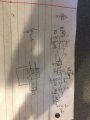
And is this is my idea for a circuit. Please let me know if it is good. So I would first have a comparator to see if the laser is shining on the photoresistor. Then there is a series capacitor with discharge resistor and series resistor. This is essentially a high pass filter for PWM. The voltage on the resistor gets measured, and must be above a certain value for a comparator to turn a MOSFET on, turning the motor on.

Additionally, I need someone to help me calculate the Rs and Cs to block less than a few Hz. Even though I can adjust the comparator, it must be within a reasonable range. And it would also need to deal with the fact that the comparator will be mostly high or mostly low, as the blade interruptions will not be 50% of the time.
 

MaxHeadRoom

Joined Jul 18, 2013
30,654
What are the details of the motor? What is CC power?
Must be a very small motor if it cannot tolerate 1a or .5a?
What coils will 'blow'?
Also talking Hz for a DC motor?
Very confusing!
Where is the circuit?
Seems like alot of overkill!
Max.
 

Thread Starter

-live wire-

Joined Dec 22, 2017
959
What are the details of the motor? What is CC power?
Must be a very small motor if it cannot tolerate 1a or .5a?
What coils will 'blow'?
Also talking Hz for a DC motor?
Very confusing!
Where is the circuit?
Seems like alot of overkill!
Max.
Sorry if I wasn’t clear. The goal is a powerful portable fan. I am first testing out the motor and seeing what it can take. I am using a smaller one because I accidentally destroyed the larger one I was going to initially use.:(

The motor is being powered by a constant current constant voltage (CC/CV) buck converter. The motor is pretty small, with thin coil wires (peeking inside). It is a little less than 1/2 in by 1/2 in by 1 in. If it is stopped and one motor coil gets all the power, it will probably heat up a lot with .5A, and blow with 1A or 2A. I want to be able to push it to the max without worrying that it will get stopped and be destroyed.

So this is my idea for a circuit. I didn’t realize how bad just a description would be.
upload_2018-8-4_17-53-46.jpeg
I have a pet oar I could do it on to make it fit reasonably and not be a mess. I would add a bypass push button to the MOSFET for startup and a slide switch in series with the battery. The battery is a liion pack designed to output a high power 12V output.

The lin reg is a linear regulator designed so the capacitor gets charged at a reasonably consistant rate. I also may just use just a zener with resistor. I may move Q1 to the output of the DC to DC converter for faster shutoff.

So I really need help choosing R5, R6, and C1. I am not sure if you want more or less discharge time, and what sort of capacitance to use. I also want R6 to be in the kΩ range.

So do you think the circuit could work to turn the motor off if there is a signal less than a few Hz? And would it work for higher frequencies?

Edit: perfboard got autocorrected to pet oar. Phones can be annoying like that!
 

Attachments

First, you can't expect a motor that takes up about a quarter of a cubic inch to make a "powerful" fan.

Second, there is no such thing as a constant current, constant voltage source. I know MPJones, and maybe others sell a board with that name, but they think you are smart enough to know that it is either CC or CV, not both.

Buy a small 5 volt fan and run it on one li-ion cell; it will work pretty well. Or get a 12 volt fan and make a 12 volt power supply.
 

Thread Starter

-live wire-

Joined Dec 22, 2017
959
First, you can't expect a motor that takes up about a quarter of a cubic inch to make a "powerful" fan.

Second, there is no such thing as a constant current, constant voltage source. I know MPJones, and maybe others sell a board with that name, but they think you are smart enough to know that it is either CC or CV, not both.

Buy a small 5 volt fan and run it on one li-ion cell; it will work pretty well. Or get a 12 volt fan and make a 12 volt power supply.
When I say powerful I mean it will cool you well if it is close to your face. Powerful for a motor that size. It does seem to be able to do that. And also the original, larger motor broke.

I did mean a PS capable of CC and CV, but not both at the same time.

I already have a 14.8V 2Ah lithium battery pack made of cells that can handle many amps. It has a 12V output designed to jump start dead car batteries (there’s some sort of circuit). I know you may need more than 12V to start a 12V battery, but I have observed that even under load the output stays around 12V. I may not even need any sort of regulator for the stopper circuitry.

So will my high pass filter work to filter out frequencies below a few Hz? And what approximate values should I use for the discharge and charge resistors? I don’t want to deal with measuring a few mV less than the supply or just a few mV. Otherwise I can adjust the reference potentiometer.

And I looked and photoresistors have atrocious response times. So I must use a photodiode or phototransistor. Could I just replace the photoresistor voltage divider with a photodiode with - to ground and + to the input? I know the voltages can be low, but would that lead to issues?

If you’re wondering why I am going through all this trouble to make this circuit, it’s because the average current through one winding will be much higher if it is stopped on that one winding. So I can use maybe 1-2A if it’s spinning fast but if it is really slow or stopped it may lead to issues.
 

Colin55

Joined Aug 27, 2015
519
Why don't you buy one of my $5,000 computers to control your fan?
It has all the PWM, synchronising, mode detection, impulse starting features you need to expedite your requirements.
 
You don't need or want a 12 volt supply for that small motor. Its was probably made to run off a 1.5 volt cell. Forget about controlling the speed just try 1.5 volts. If it is too slow try two cells for 3 volts.
 

Thread Starter

-live wire-

Joined Dec 22, 2017
959
It works fine off of 20V if it’s current limited (to prevent it from burning out if there is an excessive load). It (at 20V) only draws 1A and heats up some, with a propeller on. With no propeller, it only draws .1A. I set a safe current limit to not destroy it. I want to push it to the max to be sufficiently cooled. I will not just use 12V power, I will get a CC boost converter so that it can be more, but is current limited. The issue is if it is stopped one motor coil will get all the current, as opposed to it being about evenly distributed across all the coils. The joules on that coil will greatly increase, destroying it. One winding absolutely cannot handle 1A. The only way to detect this is by detecting if it’s spinning.

I could do this easily with a dual op amp IC, some passives, a laser diode I already have, and a photodiode. The total cost would be very small. Maybe one or two dollars. It would prevent blowing a motor, which would be VERY annoying.

I just need a little help refining the circuit. So if you have suggestions for the circuit, and how I can work through some of the issues, please share them. But please don’t say what I’m doing is dumb if you can’t understand how or why it works. And I known this stuff can be time consuming, but it’s what I like to do in my free time.

Additionally, it would give me insight into how the components work and designing such a circuit.
 
Top