Motor direction control

Thread Starter

cybertronics

Joined Aug 29, 2009
46
Steve

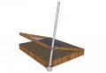
The way the lid is hinged its like a toy chest but there are no sides to attach mechanical means to the outside of the box like gas springs.
I did test with the spings when the box was not in well and it did eliminate alot of the lifting weight but the box must sit in well for drianage so you can't attach anything to the outside of the box.
I was thinking of using gas springs on the inside of the box but i have not found any that i could attach to the inside of the box, this would minimize alot of the force where i could use much less torque but I think i still will need at lease 340 to 390in lbs of torque or maybe less.So i know a mechanical leveage would help alot. and i can't use pullies and cables theres nothing to attach the cables to.

My lid dimensions are 4 feet x 3 feet 12sqft or 1728sq inches, 2pcs of 1/2 inch plywood glued together.
 

Steve C

Joined Nov 29, 2008
88
That is a very large lid! I think the servo idea is out. Even with really great mechanical advantage I think you'll end up battling gearbox noise. (weight buzz when the servo is in position)

I did have an idea last night that should solve the problem as well. SUPER mechanical advantage, lower noise than using power window or power antenna motors, lower current requirements, and all the gear should stay inside the box. I think.

What about using a pair of stepper motors attached to lead screws to simulate linear actuator operation? if you can create an assembly by which a stepper rotates a threaded nut or the like, you can push up the lid by using a pair of allthread rods.

I imagine the micro code would be somewhat more complex, but if steppers around you are anything like the motors around the surplus stores here, they are CHEAP. seriously cheap.
 
Last edited:

SgtWookie

Joined Jul 17, 2007
22,230
Have you considered using (a) torsion bar(s) on the inside of the lid?

Torsion bar(s) would take up very little room, could go inside, and would minimize the torque necessary to open/close the lid if it's reasonably balanced. Take a look at how the trunk lids on older GM automobiles use torsion bars.

Once you have the counterbalance taken care of, you could use something like the heater flap servo unit in conjunction with your temperature sensor to provide continuous adjustment of the lid's opening. Once the temperature is stabilized, the lid should just move in a fairly narrow range, and pretty slowly. You won't have sudden starts/stops like you would if it was going from fully open to fully closed.

The datasheet for ST Microelectronics' L2722 datasheet gives several examples of such controls. For example, look at figure 12 in the abovementioned datasheet.

The heater/AC door flap controller (called Blend Door Actuators) in GM autos has a small 12v motor, power opamp and circuitry built-in, where the position of the output shaft corresponds to a voltage input. There are two basic models; one for standard heater/AC controls, and one for climate-controlled vehicles. You could salvage one in a junkyard (breakers for you UK'ers) and pay around $10 US for it. They are work to get out. They are pricey to buy new.
 

Thread Starter

cybertronics

Joined Aug 29, 2009
46
Steve

What's super mechanical advantage! explain.

I was think of an car window motor nerver thought adout a anntena motor.
stepper motor nerver use them, would know where to start with that idea.
This box inside has only a clearance of only 8'' when the box is closed.

I'm also working on a smaller box and a smaller lid an any idea that I use will have to work for both boxs the smaller lid is about 17''x20'' but remember this motor set-up must work for both boxs.

Steve CAN YOU DRAW A SKETCH of this idea could work so i could picture this in 2D because i don't think using rods would work it has to open and close 0-90degrees and back down from 90-0 degrees.AND like I said the clearance in side this box is only 8''.
 

Steve C

Joined Nov 29, 2008
88
The lead screw would provide the mechanical advantage to open the lid. modern precision mechanics rely on motors attached to lead screws to control a sliding mechanism. It's like a worm gear, except the gear itself becomes a mechanical assembly. This is used in low precision electronics such as your power window motor assembly and power antenna assembly, your CD player laser position mechanism, all the way up to advanced production mechics that run at high speeds with precision in the mil range.

However, I really like the torsion bar idea. It's brilliant, and you can save yourself cash by picking one up from a pick n pull for $2 (that's what it would cost here, anyways). Integration is always easier than fabrication!

I wont draw a sketch of the lead screw idea just yet. Because a box of 8 inch depth would, for a simple design, mean that your temperature controller wouldnt be able to lift the lid much farther than that unless you located the pin near the hinge, once again requiring high torque motors. Can your temp control work with a lid that doesn't open to 90 degrees? how about 45? 20? I imagine automatic control of a couple inches of lift should be enough to temperature control the box, no?

remember, I'm suggesting you forgo the "cool" factor of manual-electronic control of the lid in favor of simply being able to lift the lid by hand to 90 degrees, saving temperature controlled position for the more useful range of motion.

-----

as for stepper control or anytime I want a 101 crash course in basic robotics, my serches include "arduino". Because that controller is tailored to less technical folks, the information generated is typically easier to digest and comprehend. Like trade school vs university. I typed "control a stepper with arduino" into bing and got many useful hits.

But really, I only mentioned steppers because my local surplus stores sell them by the barrowful for pennies, but none sell servos or high power DC motors for a comparable cost.
 
Last edited:

SgtWookie

Joined Jul 17, 2007
22,230
Well, I didn't mean to salvage a torsion bar out of an auto; it would likely have far too much tension as well as being too long to adapt to the rather small box. It's more the concept that I was trying to show.

However, some music wire aka piano wire of suitable thickness might very well do the trick.
http://en.wikipedia.org/wiki/Piano_wire
It would take some experimentation to get the length vs diameter correct for the weight over the full 90° travel.
You would also need to fabricate some sort of clamp for each end, as bending thick music wire in a tight radius may not work very well.
 

Thread Starter

cybertronics

Joined Aug 29, 2009
46
Sqt Wookie

I thought of going to junkyards and salvageyards for parts and ideas ''But there are none where i live i think the nearest one is 40miles.Its not very convenient! And I don't want too travel that far for a part they may or maynot have.

These automotive ideas are great! But this looks and sounds more complex then i want to tackle,and access to junkyards is not very accessiable where I'm located and if the part dosn't work or i need to replace it, it would be hard to find another.And i have no access to local junkyards to go and see these automobiles, and what if i can't find the type of auto you are suggesting.
Also? How is a torsion bar going to work in my application i can't see how that will work. Dose it work like a gas spring.
I used a gas spring on another project i done but i installed them on the outside of a chest i build and it works great it lowered the lifting force by half i can open the chest with one finger.
But in this new project i want too use a motor where i don't need to open it by hand. but my problem is the force vs torque on the motor and i can't use the same gas spings on the in side because the bracket on the ends are for mounting the gas spring on the sides of a box not in side. if i could find brackets that could mount the springs on the inside then i would lower my lift force to 1/10 the lifting force then i could use either a 1lb lifting servo or a samll 12vdc motor.

I'm only limited to local hardware stores, home improvement centers, and auto parts stores and the internet.
I think theres a place near me that sells used auto parts only but they really don't have much to offer. Not junkyards or salvageyards.

Sqt wookie

In your suggested idea would i still beable too use the push up/down control circuit.
Is it possible for you to draw me a sketch off how this idea would look like because i cannot picture this will work.
 

Thread Starter

cybertronics

Joined Aug 29, 2009
46
Steve.

The lid must open 0-90 degrees to access fully inside the box not 45 or 20.
The temperature control is the way i want to go thats the purpose of this project not too open the lid by hand all the time, only went i don't have to access inside the box 45 degrees would be ok to cool the box but iam not going to eliminate the 90 dg for 45 dg i need both.

If I can't get a simple sketch too see how this is too work its knid of fuzzy on how it will work in my box. ideas are good but if i can see what you are suggesting its not going to made me get to the point where i could build what you're suggesting.
You might have the mechanical ability to picture or or understand what your stating and what Sqt wookie suggested but for me i have a limited basic back ground in electronics and no back ground in mechanics but i can try to under stand tis much better if i could see a 2D IMAGE of what you're suggesting you might of build thinks like this before i haven't this is my frist project with motors and trying to come up with a simple straight forward solution.
 

SgtWookie

Joined Jul 17, 2007
22,230
4' x 3'? That's quite a large lid. Somehow I missed reading those dimensions before.

You really need something more like a linear actuator; something on the order like Steve C's talking about.

But only having the 4' by 3' dimension of the lid isn't much to go on.

Why don't you give us something to work with by drawing your box in detail, including internal clearances etc.
 

Thread Starter

cybertronics

Joined Aug 29, 2009
46
Sqt Wookie

I would of drawn a sketch went i post! don't have a scanner to scan the drawing to attach for you to see or you would of seen a sketch by now.

All i could say is the box is 4'x3' made form 1x8 poplur wood boards with a plywood lid 4'x3' thats is the same size as the box with four strong hinges on the back of the box attach too the lid to lift the lid up/dowm with a handle on the front of the lid, inside the box the internal clearance when the lid is closed is 8'' from the bottom of the box to the top of the closed plywood plexglass lid. Just picture an old school desk or a desk draw its just a narrow box with a lid'' but bigger.
I use it for seedings before i transplant to pots in the green house.

Here's an example: you will see two big wooden cedar planter boxs picture those boxs at 8'' deeper 4'x3' and a lid on top to open and close for covering the box this is the best example i could thing of.

http://www.simplyplanters.com/planter-boxes/1816+3538.cfm?source=googleaw&kwid=planters%20box&tid=phrase
 

Thread Starter

cybertronics

Joined Aug 29, 2009
46
http://www.foreverredwood.com/planters3_hd.html

This link above will show you a better picture what I'm trying too explain too you about the size of the box.
Now take my dimensions that i given you thats how big my box is plus a lid atach with hinges on back of the box.
Now the size of my box sits in a cooper well or like a narrow sink just a little bit bigger then my boxes dimensions for drainage.

http://www.simplyplanters.com/container-gardens/raised-garden-beds/raisedgarden4x8x12.cfm

this link of the box is closer to what iam taking about but my box is 4'x3' has a lid and sit in a little bigger copper well type box for drainage. once my box sit in the copper well the sides are cover so i can't attach anything to the sides and the box is bench height. around 40'' from the ground.
 

Thread Starter

cybertronics

Joined Aug 29, 2009
46
http://www.northcedar.com/raised-container-garden.html

Sorry for all those examples.

I was trying to get a example as close as possible to what i build. This link above is as close as it gets

the riased contain planter box you see in the picture in this link.
now picture a second box within this planter box with a lid on top. The riased box is the drainage part and the second box is the planter with lid if that makes sence.

thats what i have. yes you can keep them outside and my is outside but can keep them inside as i do in the winter. before i had a green house i build one of these planter boxs and put a lid on it so it act like a green house.
 

SgtWookie

Joined Jul 17, 2007
22,230
I just don't see a good simple way to accomplish your project, without adding a good bit to the original structure, and spending a good chunk of money.

Having it outside just complicates things; quite a bit. Everything will have to be rated to operate outdoors, or be in some kind of enclosure. Automotive components will take wide temperature variations, and can withstand some moisture, but aren't designed to be operated outdoors constantly.

Nothing can be added to the outside of the box. The inside of the box is full of plants and dirt and water. The 4'x3' cover will be subjected to the whims of wind and rain; any drivetrain will have to be able to not just overcome the weight of the lid, but also the forces of nature in play.

Compounding the problem is your stated novice level at both electronics and mechanical engineering, and our difficulty in extracting a complete statement from you regarding the actual parameters of the project.

I don't see this project as having a rapid or happy conclusion.
 

drc_567

Joined Dec 29, 2008
1,156
There is a type of threaded rod .... called Acme Threaded Rod .... along with its associated matching nut. The unique quality of these items is that they are made to move relative to each other.... that is the nut is designed to move longitudinally or axially along the rod, as either the rod or the nut is rotated.

The threaded rod/nut approach may be the key to generating the level of torque/force that is necessary to raise or lower the lid ..... Probably dependent upon the motor that you choose.

Another part, integral to this proposal, is a DC motor controller, as described by the link here .... an example .... but possibly relevant.:
http://www.allegromicro.com/en/Products/Part_Numbers/3968/index.asp
The motor controller should provide push button, or limit switch control, according to your design goals. .... Possibly a sensor input ... maybe light or temperature.

Although the Allegro motor controller is provided in a flat pack assembly, it should be possible to obtain an adapter board, to make it amenable to home or shop assembly.

The requirement for outdoor operation introduces the need for weatherproofing ..... and possibly the application of some sort of grease on the nut and thread assembly.


..... This is merely a general outline / suggestion .... There would certainly be additional details .... requiring design and construction.
 

Thread Starter

cybertronics

Joined Aug 29, 2009
46
I don't know what more i could give you on the on the dimensions and a close example of a picture of what it looks like. Its a box with a lid on top of a square box

the box is not completely full with dirt theres about 5'' on all four size of the box that water and dirt will not touch that hold tools

Since a motor will be used this will be on a cover porch out of the wind and rain but sun can still get in if it needs to this box is only used until the seedings are replanted into a pot thats 2-3weeks than go into the green house there are no plants permanently staying in this box. the lowest temperatures in winter is 55-65 degrees in the winter. this box will be cover. There is move inside the box for the motor but it must be no more then 4'' wide and no higher then 8'' and must be quiet.

Didn't i state theres a box within a box. so a small quiet motor can be put inside the box where the 5'' opening is on all four sides that holds tools. So i could attach something on the inside of the side boards and top on the lid only.
 

Thread Starter

cybertronics

Joined Aug 29, 2009
46
Tronster

Can you explain more to me about this Acme rod and nut how would this work for me can you give me an example and link how to apply this too a motor and my lid and Box.
Do you have a link too an example of something like i could use.
Can you draw a sketch how this would be apply to my lid to box.
 

drc_567

Joined Dec 29, 2008
1,156
Tronster

Can you explain more to me about this Acme rod and nut how would this work for me can you give me an example and link how to apply this too a motor and my lid and Box.
Do you have a link too an example of something like i could use.
Can you draw a sketch how this would be apply to my lid to box.
.... Will try to get back with a sketch ...... Not completely sure this approach will work though.... given your description of the situation.

..... I had been thinking in terms of a motor and threaded rod that would be external to the box.

.....
 

drc_567

Joined Dec 29, 2008
1,156
Attached is a rough sketch of the Acme rod and motor scheme ....
The idea is that the Acme nut is attached to the lid with a swivel, so that it can rotate as the lid is lifted. Also, the motor, at the base of the Acme rod, would be attached to the planter base with a swivel, so that it would also rotate as the angle of the rod moved .... according to the motion.

Any chance of this working?
 

Attachments

Top