 Facebook
 Google
 GitHub
 Linkedin
Hi,
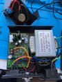
I've recently been tinkering with my first Arduino and would like to try and apply some of the things I've learned to modify a DC motor control unit and would like to ask the community for some advice.
My plan is to replace the existing potentiometer and switch with a custom control circuit that can be controlled programatically with the use of a distance sensor and some code. I come from a software background but don't have a great deal of experience with electronics so would appreciate it if anyone could guide me in the right direction.
The first step for me is understanding how the unit currently works; soo far I've hooked up my multimeter to the output terminals (+/-) which read 38v, when turning the pot I expected this value to change however it did not. So instead I measured the voltage across the pot and output terminals which did show a range between 1v - 3.3v when adjusting the pot. I assume that this voltage signal goes into the microcontroller which then generates an appropriate PWM signal to activate a transistor and then to the output terminals? Perhaps if I invested in an oscilloscope, this would allow me to see this signal?
Does this sound about right?
Attachments
-
 1.8 MB Views: 6


