Motor Clockwise for 10 sec, stop for 1 sec, counterclockwise for 10 seconds , stop

Thread Starter

mrnadimos

Joined Sep 17, 2017
12
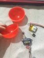
Using a push button the motor spins clockwise for a time releasing a thread from a spool attached to the motor , stop for 1 sec , then goes counter clockwise and pull the thread back and stop.
PS : i want a micro small circuit , anyone one can help me !
 

LesJones

Joined Jan 8, 2017
4,509
First you need to give some information on the type of motor you are using so we know what is required to reverse it. Also the voltage and current that the motor takes. You also need to define small. When you use the term "micro" do you mean that you want to use a microconntroller ?

Les.
 

Thread Starter

mrnadimos

Joined Sep 17, 2017
12
First you need to give some information on the type of motor you are using so we know what is required to reverse it. Also the voltage and current that the motor takes. You also need to define small. When you use the term "micro" do you mean that you want to use a microconntroller ?

Les.
The motor i am using is a micro servo motor ( witch i will transform to dc motor)
i am using a 3.7 v 15*15 mm small li-ion battery
what i meant in small and micro , is that the circuit need to be small witch can fit inside a 4.5 cm ball
thanks in advance
 

GopherT

Joined Nov 23, 2012
8,009
The motor i am using is a micro servo motor ( witch i will transform to dc motor)
i am using a 3.7 v 15*15 mm small li-ion battery
what i meant in small and micro , is that the circuit need to be small witch can fit inside a 4.5 cm ball
thanks in advance
Do you want the motor to run for a certain amount of time or for a certain number of turns (to wind/unwind the thread?
 

LesJones

Joined Jan 8, 2017
4,509
I think the most compact method would be a microcontroller (Such as a ATtiny13A or PIC12F1840) driving an H bridge motor drive IC (Such as the DRV8832 providing the peak motor current is less than 1 amp.) You could use two SPDT relay with 3 volts coils in place of the H bridge. You MAY be able to use part of the original servo electronics as an H bridge. The simplest non microcontroller solution I can think of would be a CMOS 555 IC clocking a CD4017. State 0 would drive the motor forward. State 1 would stop the motor and switch in an extra timing resistor so the 555 changed from 10 seconds per pulse to 1 second per pulse. State 2 would drive the motor in reverse. state 3 would be the static stopped state and would stop the 555 from pulsing. The push button would set the 4017 back to state 0 to start the sequence. This would run through the sequence once when first powered on.

Les.
 
Last edited:

Thread Starter

mrnadimos

Joined Sep 17, 2017
12
Do you want the motor to run for a certain amount of time or for a certain number of turns (to wind/unwind the thread?
The motor needs to run for certain amount of time , it needs to release 30 cm thread from the pool then ,then bring it back
 

Thread Starter

mrnadimos

Joined Sep 17, 2017
12
I think the most compact method would be a microcontroller (Such as a ATtint13A or PIC12F1840) driving an H bridge motor drive IC (Such as the DRV8832 providing the peak motor current is less than 1 amp.) You could use two SPDT relay with 3 volts coils in place of the H bridge. You MAY be able to use part of the original servo electronics as an H bridge. The simplest non microcontroller solution I can think of would be a CMOS 555 IC clocking a CD4017. State 0 would drive the motor forward. State 1 would stop the motor and switch in an extra timing resistor so the 555 changed from 10 seconds per pulse to 1 second per pulse. State 2 would drive the motor in reverse. state 3 would be the static stopped state and would stop the 555 from pulsing. The push button would set the 4017 back to state 0 to start the sequence. This would run through the sequence once when first powered on.

Les.
thank you Les , but i have no idea about what you are saying !! is there any map it can help me to build this process ?
 

Bernard

Joined Aug 7, 2008
5,784
There must be something on the end of the string to allow it to unspool, so let out as much line as desired; on retraction let end of line activate a switch to stop the motor ?
Circuit similar to a linear actuator.
 

LesJones

Joined Jan 8, 2017
4,509
I agree with all the comments about running the motor for the same amount of time will NOT ensure that the same amount of thread is fed out as is retracted. I think having something on the thread that triggers a micro switch at each end of the travel is a better solution. An alternative will be to have an optical encoder on the drum and count the pulses. You could then run the motor until the required number of pulses have been counted. (Incrementing a counter in one direction of travel and decrementing in the other direction of travel. I have used this system to control the travel of a roller blind. It has worked for many years without a problem. It uses a PIC16C84 which is now probably obsolete but the code could be modified to run a more modern PIC that would run on your 3.7 volts supply. As you did not understanf my post #5 I think the micro switch solution will suit you best and use two relays for reversing. The only electronics you will then need is a one second timer and a third relay.

Les.
 

Bernard

Joined Aug 7, 2008
5,784
Use the whole servo like Fitec FS 90 R, continuous rotation, 7.2 sec to unspool 30 cm. string from a about 1 cm dia. drum.
Should easily fit into 4.5 cm. ball as it's 3.2 X 3 X 1.2 cm. Should easily stop from switch with some overshoot. A PIC should work with help from others. Listed operating V as 4.8 to 6 V, @ 100 mA. May operate on 3.8 V ?? There is a short video on adafruit.
 

Bernard

Joined Aug 7, 2008
5,784
Just measured a small lever SW- 1 X 2 cm, lever 2 cm., home brew model - 6 X 8 mm, lever 12 mm; overshoot- as required but for 5 mm- a 5mm spring.
 

Thread Starter

mrnadimos

Joined Sep 17, 2017
12
I agree with all the comments about running the motor for the same amount of time will NOT ensure that the same amount of thread is fed out as is retracted. I think having something on the thread that triggers a micro switch at each end of the travel is a better solution. An alternative will be to have an optical encoder on the drum and count the pulses. You could then run the motor until the required number of pulses have been counted. (Incrementing a counter in one direction of travel and decrementing in the other direction of travel. I have used this system to control the travel of a roller blind. It has worked for many years without a problem. It uses a PIC16C84 which is now probably obsolete but the code could be modified to run a more modern PIC that would run on your 3.7 volts supply. As you did not understanf my post #5 I think the micro switch solution will suit you best and use two relays for reversing. The only electronics you will then need is a one second timer and a third relay.

Les.
I will try to figure out a circuit with the two solution u gave me , thanks man.
 

Thread Starter

mrnadimos

Joined Sep 17, 2017
12
Use the whole servo like Fitec FS 90 R, continuous rotation, 7.2 sec to unspool 30 cm. string from a about 1 cm dia. drum.
Should easily fit into 4.5 cm. ball as it's 3.2 X 3 X 1.2 cm. Should easily stop from switch with some overshoot. A PIC should work with help from others. Listed operating V as 4.8 to 6 V, @ 100 mA. May operate on 3.8 V ?? There is a short video on adafruit.
This is a picture of my components , what i need to happen exactly :

All the components needs to fit in the ball.
I will drill a small whole in the ball so the string can pass
the string will be locked on a scotch tape and attached to a table
when the push button is activated , the whole ball with the system(inside) will go down then up then stop , and each time i press the button i need it to repeat sequence .

ps : i still didn't measure how much time to motor can release and reload my 30 cm thread but i think 10 sec will do great ( not necessary to be exact 30 cm of length , just the purpose the ball needs to go up and down )
 

Attachments

Top