Motional EMF from an Electron Flow Perspective

Status
Not open for further replies.

Thread Starter

Gerry Rzeppa

Joined Jun 17, 2015
170
Slow down, please. I said:

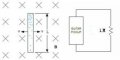
2. The rod on the left moves back and forth in a magnetic field and this forces electrons to accumulate first at one end of the rod (where the electrons meet with big resistance) and then at the other end of the rod (where they meet with equally big resistance). Yes? If not, why not?

And you replied:

No. Infinite resistance is not the same as 1 MOhm resistance. Why do you call 1M "equally big resistance"? It is not equally big. One is infinite and the other is 1 MOhm. How can you compare 1 with infinity? One is infinitely smaller than the other.
Which makes no sense. Point 2, quoted just above, is only talking about the rod in the field (the circuit on the left), not the circuit with the 1M resistor on the right. The "equally big resistance" is the resistance of the air at the bottom of the rod which is equal to the resistance of the air at the top of the rod.

But to answer your query, "How can I compare 'infinite' resistance with 1MOhm?" I reply, easily. Let's say I'm pressing down on a piece of hardwood with my thumb; my thumb squishes up a bit, and that's all that happens. Now let's say I press down, with equal force, on a piece of steel with my thumb; again, nothing happens except my thumb squishes up a bit. Did it matter that the resistance of the hardwood was significantly less than the resistance of the steel? No, because the force I'm able to muster makes both resistances effectively 'infinite' -- I'm unable to compress either one.

Next point of disagreement:

4. In both cases this varying accumulation/dispersal of electrons results in a varying potential difference across the ends of the resistances? Yes? If not, why not?

And you responded:

I already answered yes to this, but I stressed that the charge is small and inconsequential for anything important. Why are we going over the same points over and over and over again?
We're going over this again because I don't see how you can call the accumulation of of electrons in the rod inconsequential. In the oft-quoted purple description of motional EMF the accumulation of electrons is the main point -- the one and only thing that accounts for the difference in potential between the ends of the rod. It's as if you want to re-word that paragraph to read (the additions you're implying in bold):

The magnetic force acting on a free electron in the rod will be directed upwards. As a result, electrons will start to accumulate at the top of the rod, but not in any significant way. The charge distribution of the rod will therefore change, but not in any significant way, and the top of the rod will have an insignificant excess of electrons (negative charge) while the bottom of the rod will have an insignificant deficit of electrons (positive charge). This will result in an insignificant potential difference between the ends of the rod.

See why I'm confused? I'm going to stop there because there's no point in going further until we settle this issue.
 

Lool

Joined May 8, 2013
116
I still have nothing more to offer. I know my answers are basically correct and are the best I can communicate to someone that does not have formal training in field theory. If you did have formal training, you would have no confusion on these issues, and if somehow you did, I would be able to better articulate my answers in terms of equations and theory, and we would have a common language to communicate in.

I can only stress that you have very critical misconceptions in your model. There are aspects of your model that are fine, and other aspects that, while not perfect, are at least benign, if presented to a kid. However, a couple of aspects of your views will send the kid down the wrong path to understanding.

You really need to have discussions with a live person who has expertise in this area. You just are not going to get it over the internet.
 

Thread Starter

Gerry Rzeppa

Joined Jun 17, 2015
170
Let me try to simplify the question in case others would like to chime in.

Here are three devices, each with a conductive vertical bar moving to the right in a uniform magnetic field -- only in these cases the rod is sitting on conductive rails (as we often see in the textbooks):

rails 1.jpg
1. The figure on the left is essentially equivalent to the rod minus the rails, so the oft-repeated description still holds (with just a couple of minor changes):

The magnetic force acting on a free electron in the rod will be directed upwards. As a result, electrons will start to accumulate at the top of the device. The charge distribution of the device will therefore change, and the top of the device will have an excess of electrons (negative charge) while the bottom of the device will have a deficit of electrons (positive charge). This will result in an potential difference between points A and B.

The electron accumulation is shown by the gradient, where darker blue indicates more electrons per proton. A voltmeter connected across points A and B will read the maximum for the given rod length, velocity, and field strength. Current, after the initial upward surge, is nil.

2. The figure in the center is the same device except that an equally conductive rail now connects points A and B. This connection allows the electrons that are pushed to the top of the device to be quickly carried back to the bottom and the concentration of electrons is thus equalized everywhere (as indicated by the uniform shading). A voltmeter connected across points A and B will read zero. Current will be the maximum for the given rod length, velocity, and field strength.

3. The figure on the right has points A and B connected with a rail that has a significant resistance. In this case, some of the electrons motivated by the field make it through the resistor and all the way around, but some do not, leaving us with a surplus of electrons on the top and a deficit on the bottom -- but note that this surplus/deficit is greater (darker/lighter) than the equal distribution seen in the center figure, and less than (lighter/darker) the extremes seen in the leftmost figure. A voltmeter connected across points A and B will read somewhere between the maximum of the first figure and the zero of the center figure. Current will be correspondingly moderate.

Now if all that doesn't directly and logically follow from the description in purple above (which is found in textbooks everywhere, and is generally undisputed), then either I've forgotten how to read, or reason, or both.
 

Attachments

Last edited:

Lool

Joined May 8, 2013
116
Let me try to simplify the question in case others would like to chime in.

Here are three devices, each with a conductive vertical bar moving to the right in a uniform magnetic field -- only in these cases the rod is sitting on conductive rails (as we often see in the textbooks):

View attachment 89191
1. The figure on the left is essentially equivalent to the rod minus the rails, so the oft-repeated description still holds (with just a couple of minor changes):

The magnetic force acting on a free electron in the rod will be directed upwards. As a result, electrons will start to accumulate at the top of the device. The charge distribution of the device will therefore change, and the top of the device will have an excess of electrons (negative charge) while the bottom of the device will have a deficit of electrons (positive charge). This will result in an potential difference between points A and B.

The electron accumulation is shown by the gradient, where darker blue indicates more electrons per proton. A voltmeter connected across points A and B will read the maximum for the given rod length, velocity, and field strength. Current, after the initial upward surge, is nil.

2. The figure in the center is the same device except that an equally conductive rail now connects points A and B. This connection allows the electrons that are pushed to the top of the device to be quickly carried back to the bottom and the concentration of electrons is thus equalized everywhere (as indicated by the uniform shading). A voltmeter connected across points A and B will read zero. Current will be the maximum for the given rod length, velocity, and field strength.

3. The figure on the right has points A and B connected with a rail that has a significant resistance. In this case, some of the electrons motivated by the field make it through the resistor and all the way around, but some do not, leaving us with a surplus of electrons on the top and a deficit on the bottom -- but note that this surplus/deficit is greater (darker/lighter) than the equal distribution seen in the center figure, and less than (lighter/darker) the extremes seen in the leftmost figure. A voltmeter connected across points A and B will read somewhere between the maximum of the first figure and the zero of the center figure. Current will be correspondingly moderate.

Now if all that doesn't directly and logically follow from the description in purple above (which is found in textbooks everywhere, and is generally undisputed), then either I've forgotten how to read, or reason, or both.
Aside for some minor things, I have no problem with any of what you say here. It is about as good as you can do with words, and is adequate for a 10 year old kid, assuming he can understand it, which I'll say the kid is impressive if he does understand it.

I'll summarize your misconceptions in the following way. You are trying to say that case 3 is more like case 1 than it is like case 2. This is your mistake. Surely in the limit as resistance goes to infinity, case 3 becomes equal to case 1. That is true. but it does not happen at 1 MOhm. Also, it does not happen in any practical circuit case. Of course that is an overexaggeration, but we need to overexaggerate in the interest of expediency. So, for the level of concern of a kid, or anyone doing circuits, we teach them that case 3 is like case 2, and we don't even mention case 1 because it is too difficult for a beginner. If you do introduce case 1 for any reason, claiming that case 3 is more like case 1 than case 2 will take him down a road of misunderstanding and misconceptions.
 

Thread Starter

Gerry Rzeppa

Joined Jun 17, 2015
170
Aside for some minor things, I have no problem with any of what you say here. It is about as good as you can do with words...
We can get into the numbers once we're agreed on the concepts. I don't have a problem with that. In fact, we've already got one number: in case 3, if 6.28x10^18 electrons pass through the resistance every second, we've got one amp of current.

...and is adequate for a 10 year old kid, assuming he can understand it, which I'll say the kid is impressive if he does understand it.
I'm happy to report that this explanation seems both simple and intuitive to both old ladies (like my 67-year-old wife) and young kids (like our ten-year-old son). Most encouragingly, they were able to use it analytically: when I asked about the effects of "wider" and "narrower" resistances in case 3, they both correctly (and independently) predicted more flow (current) and less pressure differential (voltage drop) with the wider (lesser) resistance, and vice-versa.

I'll summarize your misconceptions in the following way. You are trying to say that case 3 is more like case 1 than it is like case 2.
No, I'm saying it's a continuum, limited at the high end by the given rod length, velocity, and field strength, and at the low end by the equilibrium state when velocity is zero.

This is your mistake. Surely in the limit as resistance goes to infinity, case 3 becomes equal to case 1. That is true. but it does not happen at 1 MOhm. Also, it does not happen in any practical circuit case.
First of all, I don't like the term "infinity." Nobody knows what it means, and talking about it leads to a great deal of logical paradoxes (like there being the "same number" of odd integers, and even plus odd integers, simply because we can map the oneset onto the other). So perhaps we can just say, "really big" or "at the practical limit" in this thread.

In the practical case of the guitar pickup, the limit is reached at about 1 megaohm. Early amp circuits sometimes used no resistor to "complete" the circuit, some ten megaohms, some five, most one. Pretty much everyone uses one meg today because there's no practical difference between one and more than one -- the limiting factor is the amount of power the pickup can muster.

Keep in mind my analogy to a thumb pressing on surfaces of various hardness -- the results are quite different with foam rubber and wood, but not much different with hardwoods and steel. Practical limits are never anywhere near "infinity."

So, for the level of concern of a kid, or anyone doing circuits, we teach them that case 3 is like case 2, and we don't even mention case 1 because it is too difficult for a beginner.
I don't see why you say case 1 is difficult. Neither wife nor kid had any trouble with "lots of people stuffed into phone booths up top (none of them able to get out) with a lot of empty booths on the bottom."

If you do introduce case 1 for any reason, claiming that case 3 is more like case 1 than case 2 will take him down a road of misunderstanding and misconceptions.
Again, I'm saying it's a continuum. That current is the flow of electrons all the way around the circuit (none in case 1, the max in case 2, more or less in case 3 depending on the narrowness of the path). Further, that voltage is a measure of the "pent up" pressure on the top versus the bottom (maximum for a given rod, velocity, and field strength in case 1, zero in case 2, and somewhere in between in case 3). I'm thinking it would be clearer if I put case 3 in the middle of the illustration.

So the current part is easy. And the resistance part everyone seems to get right away. It's the voltage concept that is harder, but I think this perspective helps to clarify it and make it not only more intuitive but more visible. Given just one principle -- that electrons (like people stuffed into phone booths) don't like to stand around together -- it all falls into place. Energy is expended moving the rod through the field which resists it, of course, and energy is expended moving the electrons through the rod and rails, but the pictures don't (and don't have to) show that -- instead they show the concrete effect of those energy expenditures, and thus the stored potential that results. The student see thus sees voltage as a measure of "the desire to get away from each other" or "the pent-up hostility between" or, more technically, "the mutual repulsion of electrons". I'm thinking a gradient that fades from red (pent up anger) at the top to blue (peaceful calm) in the middle to white (emptiness waiting to be filled) at the bottom would be a further improvement to the illustrations.

I still believe that we ought to be able to quantify voltage in these terms. Surely the more "dissatisfied" electrons (ie, surplus electrons per proton) there are in one spot, coupled with the "attractive vacancies" (protons with a deficit of electrons) in another spot, the greater the potential for getting work done. Which sounds a lot like voltage to me.
 
Last edited:

BR-549

Joined Sep 22, 2013
4,928
Gerry,

Current does not flow atom to atom. That's chemistry.

Voltage and the potential we work with has NOTHING to do with positive charge.

In the water analogy, the water comes from rain from the sky.

Atoms and protons are the sky for electrons.

It's not a ratio or difference between positive and negative charge.

It's a ratio or difference between negative charge. We only separate negative charge.

Negative charge is the only charge moving.

Negative charge is repulsive, this is why we can pressurize it.
 

Thread Starter

Gerry Rzeppa

Joined Jun 17, 2015
170
Current does not flow atom to atom. That's chemistry.
But surely chemistry and physics must agree in the end?

Voltage and the potential we work with has NOTHING to do with positive charge.
Who do you mean by "we"? Physicists?

In the water analogy, the water comes from rain from the sky. Atoms and protons are the sky for electrons.
I don't see how that helps. I'm not talking about the water analogy here. In fact, I'm studiously avoiding it.

It's not a ratio or difference between positive and negative charge.
I'm not clear what "it" refers to in that sentence. Voltage, perhaps?

It's a ratio or difference between negative charge. We only separate negative charge.
Okay, it seems "it" means "voltage". And thus voltage "is a ratio or difference between negative charge." I don't know what that means. Between negative charge and what? Other negative charges?

Negative charge is the only charge moving.
I've got that. I don't have a problem with it. The only thing moving in my drawings is electrons which have a negative charge.

Negative charge is repulsive, this is why we can pressurize it.
Again, no problem. That's exactly what my drawings and text have said. Cram more electrons into a given space (ie, more electrons per proton that you had before) and those electrons will be "pressurized". Dark blue in the pictures. Unpressurized electrons are light blue. Missing electrons are white. Like so:

rails 1.jpg
In terms you and I have discussed before, the hairnet is more compressed where the color is darker, more relaxed where the color is lighter. But I must admit I prefer thinking of the electrons as more fluid since it's hard to imagine current -- the flow of electrons -- with a hairnet.
 

BR-549

Joined Sep 22, 2013
4,928
But surely chemistry and physics must agree in the end?

Of course they do, just not with modern theory.

Electricity moves and changes charge. Chemistry moves and changes mass.

Whom to do you mean by "we"? Physicists?

Physicist do not realize the difference between + and - charge. Only polarity.

we = people that work with electricity.

I don't see how that helps. I'm not talking about the water analogy here. In fact, I'm studiously avoiding it.

I shouldn't either. I was trying to show that the atoms are only the source of electrons, not the potential.

it's hard to imagine current -- the flow of electrons -- with a hairnet.

That's because water is non-compressible and electrons are compressible.

The hairnet is to show density. The flow is like a thread on a bolt.

Only instead of a constant pitch, the pitch changes with density.

It's like a variable spring on the outside of the conductor. We can compress and expand the spring. We can vary the speed of rotation. We can change the direction of the rotation.
 

Thread Starter

Gerry Rzeppa

Joined Jun 17, 2015
170
...water is non-compressible and electrons are compressible.
By "compressible" I assume you mean that the distance between adjacent electrons can be greater or lesser. I see that. Darker blue in my drawings indicates that the electrons in that area are closer to one another; lighter that they are farther apart.

The hairnet is to show density.
Sure. I'm doing that with color, literally and figuratively: the darker the blue (the more blue pixels on the page in a given area) the more electrons.

The flow is like a thread on a bolt. Only instead of a constant pitch, the pitch changes with density.
I think I get that too. It's harder, for example, to cram more electrons into an already crammed space than to cram them into less full (or empty) spaces because the mutual repulsion is greater. Likewise, it's harder to find a white pixel on the page to color blue in the interest of darkening the gradient when the gradient is already pretty full of blue dots; the kid can see this with a magnifying glass.

It's like a variable spring on the outside of the conductor. We can compress and expand the spring.
Again, I think I get it. It's easier to compress the spring when it's not already somewhat compressed.

We can vary the speed of rotation. We can change the direction of the rotation.
There I'm not as clear. First, I have trouble picturing things in three dimensions. And secondly, I'm not sure what you have rotating -- the spring? electrons? In any case, I'm not sure it's necessary to get into rotation at the level of abstraction I'm working. After all, given these three drawings:

rails 1.jpg
We can illustrate most of the important concepts the kid needs to know quite simply. We start with the two mysterious but axiomatic givens: (1) the fact that a magnetic field pushes electrons around as the rod moves through it, and (2) the fact that electrons don't like being next to each other -- a dislike that multiplies as they get closer and closer. From there it's easy for the kid to visualize current (the flow of electrons around a complete loop), resistance (a narrowing of the path somewhere along the way), and voltage (increased pressure due to the accumulation (you, I think, would say, compression) of electrons in one spot versus another). What's more, as I mentioned in an earlier post, the student can use this mental image not only to understand simple circuits (like guitar amps), but to predict the behavior of such circuits when the values of various components are modified. I'm really having trouble understanding what there is to object to here.
 

BR-549

Joined Sep 22, 2013
4,928
That's close enough for anybody.

Remember the electrons are not jumping from orbit to orbit.

You would need a lot of copper atoms to get one free electron.
 

Thread Starter

Gerry Rzeppa

Joined Jun 17, 2015
170
That's close enough for anybody.
So far, so good, then.

Remember the electrons are not jumping from orbit to orbit.
I take that to mean "not jumping from orbit to orbit within a single atom." But they are jumping from atom to atom, yes? Kind of like this animation (which show only the outermost shell):

https://cdn.sparkfun.com/assets/9/5/6/1/4/519fcd42ce395f804c000000.gif

Except that animation only tells part of the story (the current part). The other part, the voltage part, is when those moving electrons get stuck and accumulate, more than one to an atom, yes? In other words, if the atoms in that animation were the whole of our conductive rod (case 1), no new electrons would be entering from the left, and none would be leaving at the right, and we'd end up with all of them in orbit around the rightmost atom, yes?

You would need a lot of copper atoms to get one free electron.
I'm not quite sure what you mean by that. I know there's a lot of them around since it takes 6.28x10^18 electrons moving past a given point every second to get one amp of current, and we get one amp of current in lots of places (guitar amps, table lamps, etc). And I suspect there's a similar number (of excess electrons per proton, or something like that) that represents one volt of stored potential energy.

At this point I'm thinking that one electron in the outer shell of a copper atom represents a neutral or normal state; more than one a negative state, less than one (ie, none) a positive state. Nobody here has been willing or able to tell me what the maximum number of electrons in the outer shell of a copper atom might be, but it seems to me it must be more than one. And again, it strikes me that we ought to be able to relate voltage, numerically, to this relative surplus/deficit of electrons in any two spots.
 
Last edited:

BR-549

Joined Sep 22, 2013
4,928
I'm disappointed. I thought you had it, but then you come back with the same garbage.

Current is like a shirt sleeve. The sleeve is not connected to your arm.

It's confined to an area around the arm.

It's like a straw slid over a conductor. Now make the straw out of rubber, so it can twist as it contracts and expands.

10^18 or 10^23 might seem large to you, in the context of electronics and chemistry it is but a small dozen.

That animation is bogus on all accounts. That's not current, that's ionization.

Free electrons are not acquired by electric means. They come from a phase change. When copper cools, it forms an irregular crystal structure. A small number, SMALL NUMBER of atoms will free an electron.

Those free electrons make a bee line to the surface.......never to re-combine. They do not jump from atom to atom. They make a sleeve on the surface.

A straight line of copper atoms will have no free electrons and therefore no current.

This is way too much for a 10 year old. You will have to decide how to simplify it.

We just hate to see you tell him something that is so wrong.

It really does take study in many areas to begin to grasp it all.

Unless the mystery really bites you, the neets method will suffice.
 

Thread Starter

Gerry Rzeppa

Joined Jun 17, 2015
170
Current is like a shirt sleeve. The sleeve is not connected to your arm. It's confined to an area around the arm. It's like a straw slid over a conductor. Now make the straw out of rubber, so it can twist as it contracts and expands.... Free electrons are not acquired by electric means. They come from a phase change. When copper cools, it forms an irregular crystal structure. A small number, SMALL NUMBER of atoms will free an electron. Those free electrons make a bee line to the surface.......never to re-combine. They do not jump from atom to atom. They make a sleeve on the surface. A straight line of copper atoms will have no free electrons and therefore no current. This is way too much for a 10 year old. You will have to decide how to simplify it.
If I understand you correctly, I can keep the drawing:
rails 1.jpg
But I have to make it clear, from the start, that "free electrons" (a) are not associated with particular atoms; (b) want to spread themselves evenly around the surfaces of conductors; and (c) barring outside forces pushing or restraining them, are free to move (keeping in mind that they don't want to move toward each other).

The rest of the description, I think, stays the same:

1. In the left diagram, free electrons are pushed toward the top of the device, resulting in a greater concentration (darker blue) at the top.

2. In the center diagram, free electrons are pushed toward the top but the rail connecting A and B allows them to quickly redistribute evenly around the device (hence the "neutral" blue color throughout).

3. In the right diagram, free electrons are again pushed toward the top, but the narrower rail connecting A and B allows some of them to redistribute more equally; yet we still end up with a greater concentration on the top that the bottom (as indicated by the moderate blue gradient).

Better?
 

Thread Starter

Gerry Rzeppa

Joined Jun 17, 2015
170
Excellent.....pour yourself one.
Thanks. I still have the problem of quantifying potential -- relating a particular number of volts to the particular concentration (not the number) of free electrons in a given area. For that I need both (a) a number of electrons, and (b) a measure of the amount of available space. (Fifty people in a football stadium are less concentrated than just five people in a taxicab.) That's why I was attracted (no pun intended) to the proton idea -- protons gave me a way of defining the available space. But you've taken that away from me. So how about filling in the blank? A greater concentration of electrons in one area versus another means more electrons per _________.
 

Lool

Joined May 8, 2013
116
Thanks. I still have the problem of quantifying potential -- relating a particular number of volts to the particular concentration (not the number) of free electrons in a given area. For that I need both (a) a number of electrons, and (b) a measure of the amount of available space. (Fifty people in a football stadium are less concentrated than just five people in a taxicab.) That's why I was attracted (no pun intended) to the proton idea -- protons gave me a way of defining the available space. But you've taken that away from me. So how about filling in the blank? A greater concentration of electrons in one area versus another means more electrons per _________.
I already told you that is the theory of capacitance. Stop being lazy and expecting there is a magic pill to swallow. Break out the books and learn it like the rest of us did. Once you truly understand it at a high level then maybe you will have the vision to formulate simp!er ideas that a kid can understand.
 
Last edited:

Thread Starter

Gerry Rzeppa

Joined Jun 17, 2015
170
I already told you that is the theory of capacitance.
And I still don't see why I should try to picture these three devices...
rails 1.jpg
...as capacitors. The left setup has a dielectric (air), but the "plates" have too little surface area and are too far apart for any capacitor-like behavior (ie, the air molecules are not being "stretched" one way or the other). The center device resembles a capacitor only if we picture a capacitor with the dielectric broken down and short-circuited. And the right circuit has a resistor, not a capacitor, in the loop.

Break out the books...
I have. I find Drude's model wrong but useful. Sommerfield is better because he recognizes that nothing is really continuous. The "Nearly Free Electron Model" reminds me of Br-549's hairnet -- in places (I don't want to insult him). But Band Theory and the Tight Binding Model seem to me more reasonable in their descriptions. Bottom line: It's clear nobody knows what's really happening, and almost all of these theorists are very bad at (a) drawing pictures, and (b) explaining their thoughts in plain English. Goodness! Einstein had less trouble explaining relativity to the average man. But enough of that.

---

I'm trying to find a simple relationship between what appears to be called "free surface charge density" and voltage. The colored gradients in the drawings above represent the varying densities (ie, greater and lesser accumulations of electrons). The kid can clearly see this; and he can easily conclude that there is a greater potential difference (voltage) between dark and light parts of the diagrams. At this point he has the same pictures and words in his head that I have in mine. Time for step three: formulaic values (and the formulas that relate them). We need to tell him, in terms consistent with the pictures and words he now has in his mind, what "current" and "voltage" and "resistance" mean.

Current is easy: I simply tell him that 6.2x10^18 electrons per second past a single point in the circuit is the equivalent of one amp. Then we talk about big numbers and household appliances and he gets the idea.

Voltage is what I'm working on now. How much difference in electron concentration do we need to constitute one volt of potential difference between points A and B in the drawings? I don't yet have the answer to that. But it seems a reasonable first step to get the blank in this sentence filled in: "A greater concentration of electrons in one area versus another means more electrons per _________."
 
Last edited:
Status
Not open for further replies.
Top