Facebook
 Google
 GitHub
 Linkedin
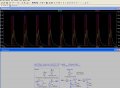
Exactly what you'd expect for a low-impedance battery being charged very slowly.the voltage across the capacitor remaining constant during the generator output interval
The waveform is virtually the same for any reasonable battery resistance, e.g. 1 Ohm.I guess this waveform would seem only reasonable with the battery having a zero series resistance
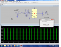
They're only a few pA in your screenshot! Probably a simulation artifact. However, I'm puzzled as to how you ran that sim; when I run it, the I(C1) current is peaking at around 24mA, not pA, at the 19-19.5 sec interval in the simrather strange glitches
 .
.