According to the datasheet the absolute maximum voltage the IC can handle is only 6.5V, so you would have to drop the voltage somehow and hence would actually be wasting a lot of the generator output by using the IC, unless you kept your speed well below 10mph . BTW, the Microchip datasheet for the IC says the startup voltage is 0.65V, not 0.9V.
According to the datasheet the absolute maximum voltage the IC can handle is only 6.5V, so you would have to drop the voltage somehow and hence would actually be wasting a lot of the generator output by using the IC, unless you kept your speed well below 10mph . BTW, the Microchip datasheet for the IC says the startup voltage is 0.65V, not 0.9V.
Thanks for your comments, Alec_t, b, but there is no slowing me down!
Minimum Start-Up Voltage VIN = 0.65, but the spec limit for the device, the max min statup V =0.8 V
Vin doesn't have much of a chance to reach over 4.18V due to the MCU code set to discharging the battery it is fully charged >= 4.18V.
In my circuit I have schottky diode from +Bat to Vout to the MCU(+5V) so the MCU can wakeup at whatever the battery voltage is when it is actually in deep sleep and BatV to Vmcu converter is disabled. This means when the condition that the battery is fully charged, the schottky diode would prevent Vin to rise above approx. 4.4V, but for a few mSec at most.
Once the converter turns on, it quickly discharges the storage capacitor, so unless the voltage would only rise a tiny bit above .65V if the battery voltage was >4.18V and in that case the MCU would discharge the Vin cap while it was also discharging the battery. The MCU simply turns all the LEDs on for a 40mA load, and this discharge load far surpasses the capability of the trickle charge effect of the generator.
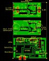
Note: some of the capacitor values shown on the PCB have been changed and likely change again as the answer to my post is being decided.
You have a misconception about how a boost regulator works. It does not just turn on and suck all the current out of the coil. It only turns on for a few 100 ns and the inductor keeps the current from rising very much in that time.
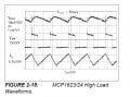
The start time is ~ 200 usec.. There is a nice curve in the data sheet.
I have to go out but I will send you a simulation so you can see the power transfer.
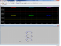
There is not a power table. Once you have the power waveform displayed on the screen go to the very top of the "scope" to the label. Then ctrl click.
At 50mA (easy with a storage cap of 4500uf) the converter turns on for about .8uSec and at the end of that interval the resistance presented by the converter would very low, a few ohms to .5 ohms, due to the peak current reached in ramping up in the 4.7 uH inductor (.8uSec on time .67V ).
In any case, the 4500uF capacitor would present only its ESR resistance to the generator source impedance.
Here is a simulation with 150 ohms in the coil. I put it inside the voltage so as not to add confusion about another 150 ohm resistor, and 3 different loads. If the load is to high (resistance to low) more than half the power is lost in the coil. If the load is to small it does not get as much power as it could. If it is the same as the coil it is Goldielocks.
Here is a simulation with 150 ohms in the coil. I put it inside the voltage so as not to add confusion about another 150 ohm resistor, and 3 different loads. If the load is to high (resistance to low) more than half the power is lost in the coil. If the load is to small it does not get as much power as it could. If it is the same as the coil it is Goldielocks.
Rightly so, but Goldilocks ended up eating all the three bear's porridge.
In any case, matching the load to the source results in maximal power transfer, but this does nothing to address the question at hand, since it does not suggest what options below would work best:
(1)boost converter, bridge rectifier, teensy-weensy bypass cap.
(2)same as above, but 4500uF cap.
(3)No boost converter, just schottky bridge rectifier.
(4)No bridge rectifier, just have-wave schottky rectiifier to battery.
(5)bridge rectifier, 4500uf cap, no boost converter.
(6)300 ohm resistor to ground, 300-ohm resistor to battery with schottky rectifer.
(7)150 ohm resistor to ground, no charging with .a perfect source-load match.
In every case there exists a varying mismatch to the source load, the load is always too low(when any boost conversion takes place or without boost converter) or too high(where no power transfer occurs, if there is or not a boost converter and/or too low generator output voltage)
case 6: there exists maybe few microseconds things are almost just right, as the generator output voltage increases, the 300 ohm to the battery remains out of the circuit until the generator voltage exceeds the diode+battery voltage, then there is a near-perfect match.
All the power is lost going into the 300 ohm to ground, less than half of the power is delivered to the battery when the generator voltage is high enough to force charging through the 300 ohm. How can this be most efficient?
Is this the best way, to most efficiently match source with load and also charge the battery?
But among all these choices there exists a best way. What is it?
Goldilocks tried them all and was only satisfied after eating them all, all without being eaten by the bears.
Somehow us Goldilocks have to live with the smelly bears.
Somewhere in a country ruled by the Great Caliph, the Grand Minister of Energy reported that it would benefit the country to save as much energy as it could, too much money was being spent paying for air conditioners and icy drink dispensers.
The Grand Minister of Energy consulted all his religious books, found no answer, and so finally, in secret, asked for help from a once most powerful man, a very religious and knowledgeable man, who was an electrical engineer who recently was sent to prison. The engineer was quick to explain that energy transfer was always most efficient when the load always matched the source impedance.
The Grand Minister left and quietly went back to the office and called the power company and asked what was the source impedance of power lines leading into all homes? The power company replied, why that's simple, it is very much less than an ohm.
So the Grand Minister told the Great Caliph and there was declared that all power was to be turned off, then that all machines, lights and other loads upon the power system must be modified to present an exact match to the impedance of the power grid.. and it was made so.
Suddenly, when power was turned on again, the city was suddenly without electricity, there was smoke and fires throughout the caliphdom, and the Grand Minister of Energy was soon without his head.
Yes, there will be a mismatch but not so big. If you run the boost IC as a constant current rather than a constant voltage you can pretty well match the load to the source.
Lets say you decide that 2 volts is the place you spend most of your time riding, for the input to the converter to look like 150 ohms it would need a current of 6.66 ma (2 / 300). (13mw)
If you want to deliver 4 volts to the battery you can supply it with 3.3 ma. So you set the output current of the regulator to 3.3ma. (13mw) Now the converter looks like 150 ohms.
You add a spall cap to the input that will keep the voltage steady for each step of the converter ~ 6.6ma, 1 usec.
The bridge rectifier is a good idea then you get 2 pulses per magnet.
No resistors of any size are needed.
But having said all that the energy is so small it probably doesn't make much difference - but you did ask for the best way.
As for the great pu pa, he should have built bigger generators.
That may be true for the second MCP1624, but the first MCP1624 has nothing to limit its Vin to 6.5V max. Also, if Vin goes above the set 4.18V the IC output is not regulated.
That may be true for the second MCP1624, but the first MCP1624 has nothing to limit its Vin to 6.5V max. Also, if Vin goes above the set 4.18V the IC output is not regulated.
To repeat, once the battery voltage drops below 4.18V by the MCU discharging the battery to prevent overvoltage charing, the first converter attempts to recharge the battery to its regulated setpoint, 4.18V and this will load Vin which can only supply a trivial small current <10mA and Vin quickly drops to <.3V and quits, and cycles up to .67V over and over, and all this happens over a few mSec at most.
Yes, there will be a mismatch but not so big. If you run the boost IC as a constant current rather than a constant voltage you can pretty well match the load to the source.
Lets say you decide that 2 volts is the place you spend most of your time riding, for the input to the converter to look like 150 ohms it would need a current of 6.66 ma (2 / 300). (13mw)
If you want to deliver 4 volts to the battery you can supply it with 3.3 ma. So you set the output current of the regulator to 3.3ma. (13mw) Now the converter looks like 150 ohms.
You add a spall cap to the input that will keep the voltage steady for each step of the converter ~ 6.6ma, 1 usec.
The bridge rectifier is a good idea then you get 2 pulses per magnet.
No resistors of any size are needed.
But having said all that the energy is so small it probably doesn't make much difference - but you did ask for the best way.
As for the great pu pa, he should have built bigger generators.
If the great pooh-pah had built bigger generators, he would hear even more people screaming in the streets and babies crying and see more smoke.
I still think that directly charging the 4500uf capacitor without any series/parallel resistor, just the converter loading, will harness the most energy over time.
Yes, there will be a mismatch but not so big. If you run the boost IC as a constant current rather than a constant voltage you can pretty well match the load to the source.
Lets say you decide that 2 volts is the place you spend most of your time riding, for the input to the converter to look like 150 ohms it would need a current of 6.66 ma (2 / 300). (13mw)
If you want to deliver 4 volts to the battery you can supply it with 3.3 ma. So you set the output current of the regulator to 3.3ma. (13mw) Now the converter looks like 150 ohms.
You add a spall cap to the input that will keep the voltage steady for each step of the converter ~ 6.6ma, 1 usec.
The bridge rectifier is a good idea then you get 2 pulses per magnet.
No resistors of any size are needed.
But having said all that the energy is so small it probably doesn't make much difference - but you did ask for the best way.
As for the great pu pa, he should have built bigger generators.
You cannot practically create a very low voltage constant current generator with even many parts, and in any case the boost converter expects to have a steady voltage source. Vin would collapse to <Vstartup and motorboat at best in useless start-stop operation.
Somewhere in a country ruled by the Great Caliph, the Grand Minister of Energy reported that it would benefit the country to save as much energy as it could, too much money was being spent paying for air conditioners and icy drink dispensers.
The Grand Minister of Energy consulted all his religious books, found no answer, and so finally, in secret, asked for help from a once most powerful man, a very religious and knowledgeable man, who was an electrical engineer who recently was sent to prison. The engineer was quick to explain that energy transfer was always most efficient when the load always matched the source impedance.
The Grand Minister left and quietly went back to the office and called the power company and asked what was the source impedance of power lines leading into all homes? The power company replied, why that's simple, it is very much less than an ohm.
So the Grand Minister told the Great Caliph and there was declared that all power was to be turned off, then that all machines, lights and other loads upon the power system must be modified to present an exact match to the impedance of the power grid.. and it was made so.
Suddenly, when power was turned on again, the city was suddenly without electricity, there was smoke and fires throughout the caliphdom, and the Grand Minister of Energy was soon without his head.
An engineer dies and reports to the pearly gates. St. Peter checks his dossier and says, "Ah, you're an engineer -- you're in the wrong place."
So, the engineer reports to the gates of hell and is let in. Pretty soon, the engineer gets dissatisfied with the level of comfort in hell, and starts designing and building improvements. After awhile, they've got air conditioning and flush toilets and escalators, and the engineer is a pretty popular guy.
One day, God calls Satan up on the telephone and says with a sneer, "So, how's it going down there in hell?"
Satan replies, "Hey, things are going great. We've got air conditioning and flush toilets and escalators and there's no telling what this engineer is going to come up with next."
God replies, "What??? You've got an engineer? That's a mistake -- he should never have gotten down there; send him up here."
Satan says, "No way. I like having an engineer on the staff, and I'm keeping him."
God says. "Send him back up here or I’ll sue."
Satan laughs uproariously and answers, "Yeah, right. And just where are YOU going to get a lawyer?"
Do you mean the first two items in that order? The rectifier serves no purpose after the converter, unless that is an AC-AC converter, also known as a transformer (still my favorite).
The purpose of the capacitor is to slightly smooth the input voltage for the converter, to a range and smoothness it can tolerate. Since the specs show it can react quickly and tolerate a lot, a bigger cap is not necessary. We can assume the person who wrote the data sheet knew what they were suggesting.
Easy to try. Probably my favorite scenario. Yes, it will only function when you go faster, but it will be effective then and that's when most of the power is available anyway.
This could be superior to #3 depending on your riding profile. Only testing could verify. If you really want to go nuts, there is such a thing as an active rectifier, which can achieve almost zero voltage drop.
I don't know if you don't understand or don't want to. There are no extra resistors in my answer. And no. If you set the regulator up as a current source rather than a voltage source it will not act like a short.
So google around constant current boost converter for a while. They are easy to make. What you have now will motor boat because it's voltage (voltage source) may be higher than the battery voltage making it draw a lot of current.
Actually all this makes little difference because you can pedal a long long time and not charge your battery much.
You cannot practically create a very low voltage constant current generator with even many parts, and in any case the boost converter expects to have a steady voltage source. Vin would collapse to <Vstartup and motorboat at best in useless start-stop operation.
 Facebook
 Google
 GitHub
 Linkedin
 . BTW, the Microchip datasheet for the IC says the startup voltage is 0.65V, not 0.9V.