There is nothing in the small schematic that shows resistor values.
What voltage and what frequency drives the 1k resistor?
What is the inductance of the load?
All the resistor values are shown.
The TS wants to know why the components are arranged in that way.
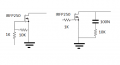
The 10K resistor in the left schematic ensures the FET is off when no signal is present. The 1K resistor is only needed if the gate to source junction ever shorted thus shorting whatever is driving the FET. Other times a resistive divider at the gate might be used if the driving signal is greater than the max voltage allowed at the gate.
The 10K and 100nf cap in the right schematic form what is called a "snubber" this is to protect the mosfet when switching inductive loads. No idea if the values shown are valid, it would depend on the actual circuit.
 Facebook
 Google
 GitHub
 Linkedin
 12.9 KB Views: 34


