Facebook
 Google
 GitHub
 Linkedin
Hello Guys,
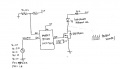
I am trying to design MOSFET switching circuit with 1MHZ Drive frequency.
I am really new to this driving circuit design so i am still at the starting stage
could any one help me how to select MOSFET for High switching frequency?
means How to estimate that a particular MOSFET is capable to handle 1 MHZ of switching frequency?