Mosfet open discussion

Thread Starter

q12x

Joined Sep 25, 2015
2,227
How do you figure that?
Well, simple, my varPSU is entering into Amp mode automatically or the short circuit protection mode when is switching from V to A blue LEDs.
Ok, at a second test, that didn't happen !!! BUT... previously I was holding in test --everything--, the mosfet and 10R for a VERY long time, probably <20min at 5V at least, and then at 6V for another <5min, while I was making the table, thinking on the formulas, etc. So it took time for 10R to heat up, enough to --and here is my biggest guess-- decrease it's resistance through temperature, and my varPSU sensors were detecting that lowered resistance and then switched into shortcircuit mode. Its the only logical thing I can think of.
At 5V you are seeing .47
By Ohms law, at 8V I expect .47 x 8/5 = .752
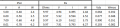
And I applaud your very keen eye, on jumping on the formulas and deducting from that what is what ! Very cool - I like it. Really - bravo.
What is it you are trying to prove anyway?
I mentioned it a couple of times already here in the forum, in writing, and also in my movies. And in the next movie that I have to edit, I only made the raw movie now, that is 2h long, but after editing will be 30min or so - I hope- haha. So Im explaining even in this last movie what I'm "proving". So stay tuned and be amazed.
- I am happy right now, that I could lift all this to this height. Thanks to everyone, but mostly to @dl324 and to my UK friend, for pointing and guiding my ass into the right direction. I have a great respect for you, so you know, officially from my mouth. ;)
Alright !
 

dl324

Joined Mar 30, 2015
18,336
Can you make a new mosfet experiment and collect the same values I have in my table here?
I question your data. In none of the tests does Vrx+Vds=Vpsu.

I tested AO3400, and maybe AO3401, at around 4-5A before. I'll test AO3400 under your conditions later.

What is the tolerance/actual value of the 10 ohm resistor?
 

Thread Starter

q12x

Joined Sep 25, 2015
2,227
I question your data. In none of the tests does Vrx+Vds=Vpsu.
Let's see, for :
5V varPSU, I got 4.64 + 0.0461 = 4.68
6V varPSU, I got 5.52 + 0.0546 = 5.57
7V varPSU, I got 6.30 + 0.0628 = 6.36
8V varPSU, I got 7.52 + 0.0752 = 7.59
So it is a bit low. Perhaps some wiring resistance - I did used some small diameter wiring in some places, connection resistance, small losses that Im used to already. But it is not sky high difference. Is acceptable losses - in my book. Is it not acceptable losses in your book? Also, there is the varPSU volt/amp-meter and my DMM volt/amp-meter, and I know they are off a bit from each other. But good eye, I didnt stop to think on this part. Thanks for raising this up.

I tested AO3400, and maybe AO3401, at around 4-5A before.
5Amps passing through this tiny mosfet? OHOHOA ! Nieeeen.... I want to see it too. Show me your setup please.
I don't believe you. Because the legs of the mosfet will melt at this amperage, not to mention its internal structure.
Hmmm - I want proof !

What is the tolerance/actual value of the 10 ohm resistor?
I really dont know it's tolerance. Probably 5%? It is a 5W 10R cement resistor. With a thick nichrome wire inside it - I presume. I never opened one either to look inside.
WOW, how lucky I am to find this one on the internet, exactly 5W 10R opened up - hahaha. Very lucky. Yah, I didnt know how its inside until now. Very interesting.
1730216337364.png
 
Last edited:

BobTPH

Joined Jun 5, 2013
11,524
Well, simple, my varPSU is entering into Amp mode automatically or the short circuit protection mode when is switching from V to A blue LEDs.
Ok, at a second test, that didn't happen !!! BUT... previously I was holding in test --everything--, the mosfet and 10R for a VERY long time, probably <20min at 5V at least, and then at 6V for another <5min, while I was making the table,
Or you had the current limit set differently.
 
Last edited:

Thread Starter

q12x

Joined Sep 25, 2015
2,227
Or you had the current lit set differently.
hmmm. I might, because I did limit it to 200mA at some point, but dont remember much after that. Usually I do jump and turn the knobs when I see that V to A switch and checking specifically if the Amp knob is too low. But maybe I was lazy that time. It is indeed a possibility.
 

dl324

Joined Mar 30, 2015
18,336
Let's see, for :
5V varPSU, I got 4.64 + 0.0461 = 4.68
6V varPSU, I got 5.52 + 0.0546 = 5.57
7V varPSU, I got 6.30 + 0.0628 = 6.36
8V varPSU, I got 7.52 + 0.0752 = 7.59
So it is a bit low. Perhaps some wiring resistance - I did used some small diameter wiring in some places, connection resistance, small losses that Im used to already. But it is not sky high difference. Is acceptable losses - in my book. Is it not acceptable losses in your book?
Not acceptable at such low currents.

EDIT: corrected 7V data. Vds off by a decimal place...
1730309896243.png
In the above, I measured Vds and calculated voltage, current, and wattage for Rx. I measured Vpsu at the drain of the MOSFET with the device off. PSU A and W were read from the supply.

I measured the load resistor (and subtracted lead resistance).
AO3400-testCkt.jpg

Grounding strap:
groundingStrap.jpg
 

Attachments

Last edited:

dl324

Joined Mar 30, 2015
18,336
5Amps passing through this tiny mosfet? OHOHOA ! Nieeeen.... I want to see it too. Show me your setup please.
I don't believe you. Because the legs of the mosfet will melt at this amperage, not to mention its internal structure.
Hmmm - I want proof !
Measured using the PWM circuit.
1730222174754.png
 

Thread Starter

q12x

Joined Sep 25, 2015
2,227
I dont have a 10R 50W. Thats why you can do this and I can not.
I only have 0.2R and 1R at 50W.
and that 10R at 5W.
But interesting results. For the continuous reading at least.
--- I commanded a 0.1R, 1R, 10R, 100R, at 100W now. Only these 4 resistors cost me $5.88. Aaahh...
 
Last edited:

dl324

Joined Mar 30, 2015
18,336
I dont have a 10R 50W. Thats why you can do this and I can not.
The MOSFET wasn't on long enough for that to make a difference.

Something else was causing your power supply to go into CC mode. You had previously done an experiment with it set to 200mA; even that wouldn't have caused what you observed because it only the readings at 7 and 8V were affected.
 
Last edited:

dl324

Joined Mar 30, 2015
18,336
@q12x The component holder in the video doesn't appear to be ESD safe. Personally, I keep ESD sensitive components in the original packaging until I'm ready to use them.
 

Thread Starter

q12x

Joined Sep 25, 2015
2,227
The component holder in the video doesn't appear to be ESD safe.
Yes I'm aware about that too. But so far nothing got damaged from using it for more than 10years. Only when Im putting my fingers is the problem. They work fine from that holder if Im careful handling them. Especially those super sensitive 2N7002. If were true what you say, that the holder is a ESD problem I should have got them already damaged when taking from it, but nothing was like that, at least to my observations. I trust it is good enough. Thanks for watching. I didnt add in the movie anything more than what we discussed here.
I also start to believe there are mosfets --without-- ESD protection and --with-- ESD protection, build in. I believe, my IRFZ44N they have ESD protection because I can touch it's gate fine, while those SMD's I have get destroyed. Usually for logic ICs I seen ESD protection mentioned 1kV -2kV normal for human handling. But I dont remember although I think I look for this detail specifically, on mosfets to have it specified.
You also mentioned some time ago about logic mosfets with probably 5V on their gate. Right? Can you suggest to me what you used and what you think is best from your experience with them? Also if they are ESD safe if you happen to know.
- I am thinking on a mosfet protection circuit right now, since I asked here and I got no answer. I am thinking on adding a zenner protected by a resistor and thats it. I hope its that simple. Ill have to experiment. Especially for A09T SMD ones. I also have TVS diodes, they are like zenners but for kV range, usually put on inputs to protect from HV spikes. I also seen TVS diodes used as protection for Gates on mosfets as well, so its not quite a novelty for me.
 
Last edited:

dl324

Joined Mar 30, 2015
18,336
But so far nothing got damaged from using it for more than 10years.
Consider yourself lucky (or unlucky because all of the devices are now suspect).
I believe, my IRFZ44N they have ESD protection because I can touch it's gate fine
They don't have built-in ESD protection, but the higher gate capacitance helps.
Usually for logic ICs I seen ESD protection mentioned 1kV -2kV normal for human handling.
I believe that's the human body model.
You also mentioned some time ago about logic mosfets with probably 5V on their gate. Right? Can you suggest to me what you used and what you think is best from your experience with them?
Logic level MOSFETs typically have threshold voltages significantly below 3V; like AO3400/AO3401.
Also if they are ESD safe if you happen to know.
Very few MOSFETs have built-in ESD protection. NTA4151P is one. It has a protected gate, but not S/D.
 

Attachments

Last edited:

Thread Starter

q12x

Joined Sep 25, 2015
2,227
Very few MOSFETs have built-in ESD protection. NTA4151P is one.
That is a P-channel. I find the complementary of it, the N-channel NTA4153
This mosfet looks to me that is also a logic mosfet too, with a VGS=6V ! Very interesting.

Logic level MOSFETs typically have threshold voltages significantly below 3V; like AO3400/AO3401.
Are you sure AO3400 is a logic mosfet? its VGS = 12V. It should be 5V (or 3V).
1730520688602.png
 
Last edited:

Thread Starter

q12x

Joined Sep 25, 2015
2,227
I have found another 3 ESD internal protected mosfets !
your NTA4153, then CSD17381F4, NCV8440, DMN61D8LQ, DMP3007SFG, Look at their internal diagrams.
DMN61D8LQ is very interesting ! The gate Voltage is also -voltage divided- by those 2 resistors !
Aaaaaaa - they actually specify that is a logic driven mosfet !!! Although the general characteristics, VGS, VDS, IDS, and the rest are very similar with the rest of the GPMOS(general purpose mosfets), including the ones I have in my arsenal. 1exception is the RDSon resistance, for this one is very big, 1.8Ω -2.4Ω. I can see almost all the data is in respect to VGS at diferent values.
1730523795075.png
 
Last edited:

Thread Starter

q12x

Joined Sep 25, 2015
2,227
ok, can you explain what it means to you? This Gate Threshold Voltage? Why you insist on it, and not VGS ? How you see it's significance? I already made my homework about it. So Im very curious whats your interpretation.
 
Last edited:
Top