 Facebook
 Google
 GitHub
 Linkedin
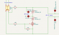
I have built an Arduino controlled macro photographic stage setup and I use a Mosfet switch circuit (see attached) to switch two DC 10Watt LEDs on for 2 seconds that act a flash while a photo is taken. The system works well to photo insects.
The 10 Watt LEDs are powered via a buck converter set to 11V/0.9Amps. The system works rather well, measuring the volts/amps across the LED Lights terminals give zero when off and peaks at 10.2v/0,85amps during the 2 seconds of being on with LEDs connected as expected.
The system does not work that well for black or dark objects so I swapped the original LEDs for 2 50Watt LEDs to increase the light levels.
This works in a similar way powering the LEDs with a boost convertor set to 30V/0.6Amps. Measuring across the terminals during the 2 seconds peaks at 29.8V/0.6Amps However, when off there is 15.8V/0Amps across the terminals and a few of the individual LEDs on the 50Watt chip are just starting to light although not current is flowing as measured with Digital Multi-meter on mAmp setting.
I’ve checked through the mosfet threads but can find an explanation of a voltage drop across the source/drain when a Mosfet is off so can anyone explain why is there this voltage drop for the 50Watt LEDs. I would have thought is should also be zero as the 10Watt LEDs as the Id & Dsd are still in the safe operating area according to the IRLZ44N data-sheet.
Is the Mosfet leaking across source and base?
Should I be using a different Mosfet? If any suggestions?
Are the resistors I’m using wrong?
Thanks Daniel.
Attachments
-
 6.7 KB Views: 21
") .
.


