Mosfet magic smoke

Thread Starter

nitrochicken

Joined Mar 7, 2008
25
I have a pedal kettler gocart that I've converted to electric for my young kids

It uses a brushed 350w 24v geared motor and is powered by some paralleled 6S 18650 packs that I made up.

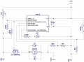
The control unit uses a picaxe 08m2 to input throttle(from a potentiometer in a foot pedal) and outputs a PWM signal at 10kHz to a mosfet to power the motor.
It also has the main battery connected to an input via a voltage divider to monitor battery voltage and prevent over discharge of the battery
The motor has a freewheel diode connected across its supply along with a small(can't remember its value) ceramic capacitor.
I have an emergency stop button that breaks the supply to the control circuitry

Today was its first outing and it was working great for about 40 minutes when suddenly it went out of control and the motor turned full on with my 4 year old daughter on board. Luckily it doesn't go too fast and I was only a few feet away so I quickly pressed the stop button only to find that it kept on going...... scary moment!
I had to lift up the back of the gocart and disconnect the battery to make it stop. My daughter was ok but a little scared.

When I got it home I opened up the control unit to find(and smell) that the mosfet had burned out and failed on. It had also fried the 08m2 as I assume it sent 24v to the gate.


The mosfet I used, STP36NF06L, is heatsinked and is rated at 60v and 36A. The motor states 24v 18.5A on its case so I thought there would be no problems here and the mosfet would handle it.

My next step now would be to purchase a higher capacity mosfet but I worry that there might be something else going on here as it was only run at approximately 50% duty cycle today.

I also need to change the stop button to make sure it cuts power to the motor not just the control unit, I think using a relay.

Any thoughts on this, why did the mosfet fail? Have I missed something?

Sorry for the long post but I know from experience that it is better to have plenty of details
 

TechWise

Joined Aug 24, 2018
151
Couple of questions:
  1. What are the details of the gate driver? Do you have a schematic of your circuit?
  2. Have you verified that the switching signal coming out of the microcontroller is as you expect? It's easy to make a mistake with the programming and end up switching at a much higher frequency than you intended. (Been there, done that)
  3. How did you size your heatsink? The power loss will be made up of the on state conduction loss and the switching loss which is not so easy to calculate.
Also, it may be a good idea to use an isolated gate driver and/or optoisolation between the control and power circuitry. Saves a new microcontroller if something like this happens :oops:
 

Thread Starter

nitrochicken

Joined Mar 7, 2008
25
I don't have a schematic to hand, it was originally drawn on paper and it has gone missing! I will attempt draw one up in ms paint.

The mosfet is a logic level model and is driven directly from the picaxe

I've just checked the PWM frequency using the picaxe pwm wizard and it is not 10000Hz but 14926Hz. I think this should still be OK though?

The heatsink was not sized but is just what I had. Its approx 75mm x 75mm x 15mm with several fins. I think it originally came from an old graphics card. The mosfet is bolted to it with some thermal paste between them.

Optoisolation is new to me, how does this work?

Thanks
 

crutschow

Joined Mar 14, 2008
34,464
The rise/fall times from the picaxe to the MOSFET may be too slow due to the high gate-capacitance of a MOSFET.
You may need to add a gate driver circuit.
The six paralleled input/outputs of a CD4050 hex non-inverting buffer can work as a poor-man's driver.
 

TechWise

Joined Aug 24, 2018
151
I don't have a schematic to hand, it was originally drawn on paper and it has gone missing! I will attempt draw one up in ms paint.

The mosfet is a logic level model and is driven directly from the picaxe

I've just checked the PWM frequency using the picaxe pwm wizard and it is not 10000Hz but 14926Hz. I think this should still be OK though?

The heatsink was not sized but is just what I had. Its approx 75mm x 75mm x 15mm with several fins. I think it originally came from an old graphics card. The mosfet is bolted to it with some thermal paste between them.

Optoisolation is new to me, how does this work?

Thanks
As @crutschow said before me, even though the MOSFET is "logic-level" you still need to provide sufficient current to charge and discharge the gate capacitance of the MOSFET to ensure that it turns on and off quickly, thereby reducing your switching losses.
Optoisolation refers to using light to transfer a signal from one point to another without using a direct electrical connection. It means that a voltage spike or other hazardous condition in your power circuit is not able to propogate back into your expensive control circuitry!
 

Sensacell

Joined Jun 19, 2012
3,453
15 Khz PWM from an IO pin driving a power MOSFET gate...

The FET is going to switch slow, spending too much time in the linear region, where it dissipates power.

The IO pin cannot push / pull the current required to charge and discharge the gate capacitance quickly.

Investigate gate driver IC's. Some of them are rated in amps of output current- that's what it can take to get fast switching.
 

crutschow

Joined Mar 14, 2008
34,464
Below is the schematic and LTspice simulation for a CD4050 as a gate driver.
It should be sufficient to efficiently drive the MOSFET you are using, which has a reasonably low gate capacitance.
The Vdd is for the CD4050 power.
Be sure to connect a 100nF ceramic capacitor directly across the IC power to ground pins (not shown).

upload_2019-1-15_20-21-6.png
 

dl324

Joined Mar 30, 2015
16,943
Why not just get & use a standard YK31 speed controller for brushed motors?
Here is one for ~$23.00 delivered, it even has a reverse function.
Because it doesn't make sense to pay more than you need to and it isn't very smart to pay for features that you don't need.
 

Thread Starter

nitrochicken

Joined Mar 7, 2008
25

Alec_t

Joined Sep 17, 2013
14,330
The mosfet I used, STP36NF06L, is heatsinked and is rated at 60v and 36A. The motor states 24v 18.5A on its case
There's most likely at least part of the problem. At start-up the motor is in a stalled state and will draw many times its rated running current. Methinks you need a much beefier MOSFET, or else several parallelled.
 

TechWise

Joined Aug 24, 2018
151
There's most likely at least part of the problem. At start-up the motor is in a stalled state and will draw many times its rated running current. Methinks you need a much beefier MOSFET, or else several parallelled.
....also perhaps a limit in the controller code to ensure that the duty cycle is ramped up and down gradually to reduce peak currents during startup.
 

MrSoftware

Joined Oct 29, 2013
2,202
Side note; if your processor has the resources to spare, maybe it's worth adding a thermocouple to your heatsink and log the temperature. This way if it happens again you will have some data to go on. Maybe grab the temperature every 10 seconds or something. If your processor has any analog input lines then you can read the thermocouple directly, or get an ADC with a friendly interface like I2C or SPI, etc..

Or, maybe better is add a dedicated thermal protection circuit. If the heatsink reaches some preset temperature, pull the gate to ground so it cools off before it fails.
 
IMO ~$20.00 for a safe component is a small price to pay, especially for a kids safety.
This DIY one (as many do) has already got stuck "full on" & if it was any faster, it would of took off with his kid.
(out into the street, into a wall...who knows)
If continuing down this DIY speed controller path, I would at the very least install a remote kill switch.
If it gets stuck again, you might NOT be so lucky, next time.
 

Thread Starter

nitrochicken

Joined Mar 7, 2008
25
IMO ~$20.00 for a safe component is a small price to pay, especially for a kids safety.
This DIY one (as many do) has already got stuck "full on" & if it was any faster, it would of took off with his kid.
(out into the street, into a wall...who knows)
If continuing down this DIY speed controller path, I would at the very least install a remote kill switch.
If it gets stuck again, you might NOT be so lucky, next time.
Citywide, thanks for your concerns with regards to safety.
I already have a emergency stop button in easy reach. This will be changed to cut the battery supply completely when pressed in, previously it only cut the 5v supply to the microcontroller.
The gocart only travels at a walking pace at full speed and will not be operated near any roads or cars.
A remote kill switch is a great idea, I will look into this. Maybe I could use a RC TX/RX somehow.

Side note; if your processor has the resources to spare, maybe it's worth adding a thermocouple to your heatsink and log the temperature. This way if it happens again you will have some data to go on. Maybe grab the temperature every 10 seconds or something. If your processor has any analog input lines then you can read the thermocouple directly, or get an ADC with a friendly interface like I2C or SPI, etc..

Or, maybe better is add a dedicated thermal protection circuit. If the heatsink reaches some preset temperature, pull the gate to ground so it cools off before it fails.
Hi MrSoftware,

I'm afraid I've used up all of my inputs on my picaxe 08m2.
I also do not think it has the capability of storing information after powering off.
I could probably manage to create a program that monitors temperature and cuts the output but I would need a different microcontroller for this with more inputs.

....also perhaps a limit in the controller code to ensure that the duty cycle is ramped up and down gradually to reduce peak currents during startup.
I think the throttle pedal should deal with this somewhat. It is quite progressive and has a large throw so it should not travel from 0-100% duty cycle too quickly
 
Last edited by a moderator:

Thread Starter

nitrochicken

Joined Mar 7, 2008
25
Below is the schematic and LTspice simulation for a CD4050 as a gate driver.
It should be sufficient to efficiently drive the MOSFET you are using, which has a reasonably low gate capacitance.
The Vdd is for the CD4050 power.
Be sure to connect a 100nF ceramic capacitor directly across the IC power to ground pins (not shown).

View attachment 167940
Hi crutschow,

Thanks for the information and schematic.
I think I would be able to implement a gate driver quite easily, as well as increase the capacity of the mosfet.
If I were to use a gate driver, would this protect the microcontroller if the mosfet were to fail again?
Is the CD4050 the best way to do this or is there a better alternative?

Do you, or does anyone have any mosfet recommendations? The one I was using was a TO-220 but is there a more suitable/robust package maybe with larger heatsinking area?

Thanks
 
Top