MOSFET Heating Problem

praondevou

Joined Jul 9, 2011
2,942
Another thing is that our supply to the MOSFET is only limited to 1A current. We are using the PB150S DC-DC Converter as a supply to our MOSFET and this component has a maximum output current of only 1A so even if the current limiter is not working the supply will still limit the current to 1A only.
If it's a DCDC converter then it has a capacitor at the output. Normally the converter deosn't have a control over the discharge of this capacitor, so yes, it will limit it's regulation to 1A but the output capacitor could very well provide much more than this.

Look, do us a favor and provide at least this data:

1. Waveform on the 1R current limiter resistor.
2. value of the capacitor connected to the MOSFET.

There are thousands of working MOSFET switching circuits on the internet, so there is absolutely nothing confidential about it. You could make a hand-drawing of the

1. MOSFET, capacitor, resistor combination
2. Gate drive and gate resistor

EDIT: I just had a look to see if there is a "better" MOSFET outthere, as you requested. I can't find any. Wow, you found the most powerful p-channel MOSFET and you destroyed several of them. Don't you think it's time to revise your circuit? ;-)
Is this a prototype or is this going into production?
 
Last edited:

SgtWookie

Joined Jul 17, 2007
22,230
OK, if your supply can't provide more than 1A, then all you need to do is replace the current sense resistor with a piece of wire, and let the supply do the limiting.

What's happening now is that the current limiting scheme is keeping the MOSFET in the linear region. The MOSFET simply can't turn on or off all the way. So, it's trying to dissipate 150v*1A Watts, or 150 Watts all the time - it decreases as the capacitive load charges, but at 150W without really, really good heat sinking, you won't be able to keep the MOSFET cool enough.

Replacing the current sense resistor with wire will effectively disable the current limiting portion of the circuit.
 

Thread Starter

Engr

Joined Mar 17, 2010
114
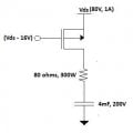
We revised our circuit. The circuit that we have now is similar to the circuit on the attached file. With this circuit, the MOSFET is not heating up but the resistor connected on the drain of the MOSFET is the one heating up. Can anyone explain why? The Resistor is rated 300W and base on the computation with 1A current passing through the 80 ohms resistor, the dissipated power is only 80W but it is heating up so much.
 

Attachments

kubeek

Joined Sep 20, 2005
5,796
How about bringing your o´scope out of the closet and doing some measuerments? For instance, GS voltage and voltage across the 80ohm resistor in one picture would be nice.
 

SgtWookie

Joined Jul 17, 2007
22,230
Even 80 Watts is a lot of power to get rid of.

If you don't have plenty of air circulating around the resistor, it will keep getting hotter until it burns up.

If you went to a synchronous buck regulator using an inductor instead of resistors, you would not have this heating problem.
 

Thread Starter

Engr

Joined Mar 17, 2010
114
Even 80 Watts is a lot of power to get rid of.

If you don't have plenty of air circulating around the resistor, it will keep getting hotter until it burns up.

If you went to a synchronous buck regulator using an inductor instead of resistors, you would not have this heating problem.
I tried replacing the resistor with a inductor but it didn't work. What happened when I use an inductor is that when the MOSFET turn on, the voltage on the Source will be pulled by the voltage on the Drain (0V at start) and will turn off the MOSFET since the Gate voltage will now be higher compared to the voltage on the Source. I think having a proper air ventilation and heatsink on the resistor is the solution on this problem.
 

SgtWookie

Joined Jul 17, 2007
22,230
Simply replacing the resistor with an inductor did not work, because the existing circuit does not monitor current past the drain; only current flowing from the supply across the sense resistor into the source terminal.

As soon as the current through the resistor drops below 1A, the existing circuit immediately turns the MOSFET back on, whereupon the current through the resistor immediately exceeds 1A again, causing the circuit to turn the MOSFET off again, and the cycle repeats until something overheats. Since the circuit will be turning the MOSFET on and off as fast as it can, the MOSFET will spend most of its' time in the transition state, where it has a relatively high resistance, and it will dissipate power as heat.

The existing design is poor. It needs to be re-designed. Until it is re-designed, you will be dissipating a lot of power as heat. If it is cold where you are, then maybe the heat is a good thing.

I've already gone over this several times with you, and I'm starting to think that you just don't want to listen.

I have already shown you how to fix the design, yet you keep trying other things that don't work.

Do you want to fix the problem, or not?
 

Thread Starter

Engr

Joined Mar 17, 2010
114
Simply replacing the resistor with an inductor did not work, because the existing circuit does not monitor current past the drain; only current flowing from the supply across the sense resistor into the source terminal.

As soon as the current through the resistor drops below 1A, the existing circuit immediately turns the MOSFET back on, whereupon the current through the resistor immediately exceeds 1A again, causing the circuit to turn the MOSFET off again, and the cycle repeats until something overheats. Since the circuit will be turning the MOSFET on and off as fast as it can, the MOSFET will spend most of its' time in the transition state, where it has a relatively high resistance, and it will dissipate power as heat.

The existing design is poor. It needs to be re-designed. Until it is re-designed, you will be dissipating a lot of power as heat. If it is cold where you are, then maybe the heat is a good thing.

I've already gone over this several times with you, and I'm starting to think that you just don't want to listen.

I have already shown you how to fix the design, yet you keep trying other things that don't work.

Do you want to fix the problem, or not?
I followed one of your advice where we used the inductor, it worked but the problem is that the charging time is taking too long. What worked on our set-up was the resistor transfered to the Drain of the MOSFET and change the value to 80 ohms. We also removed the circuit that is sensing the current since our supply has a maximum current of 1A so we let our supply limit the current flowing in the circuit. Now that the resistor is heating up, you advised to use a heatsink and it must have a proper ventilation so that is what we did as of now. The heat dissipated by the resistor has somehow subsided. We cannot make a major revision on our circuit because when the circuit was given to me it is already fabricated on the board and that is one of my limitations. If the circuit can be re-designed then I could have followed all your advice but since the circuit is already existing and the board is already fabricated the changes that I must make must have less modifications.
 
Top