 Facebook
 Google
 GitHub
 Linkedin
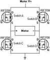
The N channel in Figure MOSFEF operate under ON-OFF to put the DC motor to rotate in either direction, as polarity of the voltage applied to it.
Assuming that each gate can apply one of the following voltage values: VK> VT or 0 V, determine the combinations of 4 voltages (VA, VB, VC and VD) that must be applied to the gates of each transistor so as to put the engine running in each senses.
So when we have VGS>VT, this will make a current flow through IDS right?
So i suppose if we want the motor to rotate in one direction we wiil have to apply Va>VT ,Vb=0,Vc=0, Vd>VT and for the motor to rotate in a different direction we will have to apply Va>VT,Vb=0,Vc>VT and Vd=0,right?
What is the function of the diode conected between the Drain and the Source of the MOSFET?
Thanks
Attachments
-
 24.7 KB Views: 35
Last edited:


