Facebook
 Google
 GitHub
 Linkedin
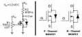
One of the common phrases I live by is it ain't what folks know that gets them in trouble it's what they know that ain't so ( courtesy of Mark Twain). I just ran into that big time with a MOSFET. I always thought MOSFETs had a linear region it was just very very hard to reach, apparently not. I verified this to myself with this experiment, which failed miserably. Oh well, back to the drawing board.

basically using a 10 turn pot I was unable to hit anything other than a one or a zero on the output.
basically using a 10 turn pot I was unable to hit anything other than a one or a zero on the output.
Last edited: