MOSFET Blows upon giving 230VAC Mains

Thread Starter

SJZ

Joined Oct 12, 2022
8
Hello,

I am trying to design a High Power Classic Boost PFC board which is currently at testing.

(To test the main circuit first without the controller circuit)

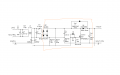
First I checked the Inrush circuit with Bridge Rectifier, Inrush diode and Electrolytic Bulk Caps and and was successfully able to get peak dc value at the output(325V no load) (Consider the following circuit as an example)

1683270851046.png
Then in the second test I assembled the complete circuit including the Inductor, Boost Diode and Mosfet.

But after providing the isolated AC mains, MOSFET is failing (all leads short) and the MCB trips to stop the Mains. (still at no load). Even when no gate signal is provided to MOS, so no switching.

1683270924687.png

The MOSFET I am using is: https://www.infineon.com/dgdl/Infineon-IPW60R060P7-DS-v02_00-EN.pdf?

I replaced the MOS with fresh one. And for a low voltage test to check MOS, provided 50% fixed duty generated wave to MOS at 20V and got expected Boosted voltage at output.

Then why is the MOS failing at 230V input at No load by just sitting there? (With no Switching condition due to absence of any gate signal)
Most parameter looks correct to me, I wonder if it is happening due to inrush or body diode failing?
Is there something I am missing?
 

Attachments

Ian0

Joined Aug 7, 2020
9,847
The MOSFET gate should be driven by a low impedance. 10k pull-down resistance isn‘t low enough to prevent the gate-drain capacitance from switching it on. It should start up properly if the gate is directly connected to the source.
 

Thread Starter

SJZ

Joined Oct 12, 2022
8
Hello Ian, thanks for the reply.

As per my understanding, the pull down resistor is used to keep the MOSFET turned off during startup.
Also 10k is a pretty standard value for pull down resistor and can be seen to be used in most of the designs.

So I dont see how it maybe causing any problem to MOS which is not switching(not in operation)
 

Ian0

Joined Aug 7, 2020
9,847
Hello Ian, thanks for the reply.

As per my understanding, the pull down resistor is used to keep the MOSFET turned off during startup.
Also 10k is a pretty standard value for pull down resistor and can be seen to be used in most of the designs.

So I dont see how it maybe causing any problem to MOS which is not switching(not in operation)
Startup refers to the time it takes the control IC to start. After the control IC gets more than its UVLO voltage (say about 15V) it will be operating, and clamping The gate voltage to 0V. The body diode of the upper MOSFET in the gate driver will also conduct any charge that has arrived via the power MOS gate-drain capacitor into the auxiliary supply smoothing capacitor.
 

Thread Starter

SJZ

Joined Oct 12, 2022
8
Thanks, I will try that out.
Actually some test process mentions that the circuit should withstand the AC without any controller, gate drive or gate signals.
So even without driving the gate at all(gate pin - open), the failure of mosfet is concerning me before proceeding ahead
 

Ian0

Joined Aug 7, 2020
9,847
Thanks, I will try that out.
Actually some test process mentions that the circuit should withstand the AC without any controller, gate drive or gate signals.
So even without driving the gate at all(gate pin - open), the failure of mosfet is concerning me before proceeding ahead
Short the gate to 0V, then try it. If it fixes the problem, then the problem was due to capacitive coupling into the gate via Cdg.
 

ronsimpson

Joined Oct 7, 2019
3,052
Years ago on the first PFC circuits we did not understand that D1 is important. It keeps L1 from ringing at power up and saturating at power up. The ringing makes over voltage on C4 and indirectly on Q1.
If RT1 is in place the voltage rise time on C4 and Q1 should be slow enough to not turn on Q1, so I think R2 10k is OK, but I agree with Ian0 that it is easy to test.
1683305009987.png
 

Thread Starter

SJZ

Joined Oct 12, 2022
8
Thanks for all the suggestions, I provided gate pulses to the MOS and the circuit started operating correctly.

However, quick update, it worked till 1.6kW(65% load) then suddenly the circuit failed when the Boost diode exploded and MOSFET all legs shorted.
- I doubt if Inductor saturation is the reason here.
- My MOS and diode are on same heatsink but insulated by a thermal tape. So now I am checking if it happened due to thermal breakdown.
Anyways, I reassembled and tested circuit again but it failed similarly at 1.2 kW (lower load than before)
Now one of the non technical differences between two tests is in first test my through hole diode was more deeply soldered in PCB(that is die more closer to PCB) than in second test.

- So I am wondering if the diode leg not able to take current completely is leading to the explosion of the diode which then result in shorting of MOSFET?
- Do diodes generally explode in thermal breakdown conditions?
The diode used is: https://www.infineon.com/dgdl/Infin...N.pdf?fileId=5546d4625cc9456a015cd505b4ec2e17
 

ronsimpson

Joined Oct 7, 2019
3,052
However, quick update, it worked till 1.6kW(65% load) then suddenly the circuit failed when the Boost diode exploded and MOSFET all legs shorted.
Please find a data sheet for the inductor. I can't find it. Sounds like the inductor saturated.
 

Thread Starter

SJZ

Joined Oct 12, 2022
8
Hello,
Hope you are having a nice day.

The core I am using is a powder core: https://www.mag-inc.com/Media/Magnetics/Datasheets/0077083A7.pdf
I have stacked two of them and these are the design specs / calculations(attached)
My doubt is the min. inductance at specified current on the online calculator is coming out to be 140uH which is far less than required inductance (290uH-340uH)
But the same Inductor is used in the following reference design and it is working on that board(pg. 17): https://www.infineon.com/dgdl/Infin...N.pdf?fileId=5546d4624fb7fef2014fd65081616257
They are using the design for 230Vin(2.5kW) same specs, just with different controller ICs
 

Attachments

Top