Monostable + Transistor Switching Circuit does not turn off/work

Thread Starter

Tdyne

Joined Mar 21, 2016
3
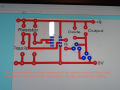
Hey guys. So I do DT Systems and Control GCSE level, and I'm completely stuck on my coursework. I've been trying to get my circuit right and working the past few days but I just can't identify the problem. I go to a boarding school and our holidays start in two days, therefore, my due date is basically in two days. So onto the problem. My circuit is a monostable 555 timer which is connected to a transistor switching circuit. What happens is there is a pressure pad which someone steps on, and the circuit is meant to turn a motor to turn a platform. At first, the motor didn't even turn on, and I had absolutely no idea why. So I just desoldered various components like the capacitor - which I replaced with another one - as well as the diode which I replaced with an LED. That was a bad idea as it seemed the transistor and the LED was overheating as a result, but I did find out that when I touched the collector and base (of the BC108) together, the LED turned on and the motor turned! So I resoldered the diode back in and thought about doing something I know is absolutely crazy, but I was just so desperate. I put a little bit of solder between the collector and base so they were connected, and the motor turned! Now, this led to other massive problems. First of all, the circuit now does not even switch off, and secondly, the circuit doesn't turn on only when I step on the pressure pad, it turns on immediately after I connect the battery. So, someone please help me as I am so stuck and only have pretty much two days left. Oh god....

PS: My circuit is a PCB with copper
 

Attachments

Jony130

Joined Feb 17, 2009
5,487
I do not have time to read your very long post. But do you know that if the TRIGGER input is held low for longer than pulse length, it will keep the OUTPUT high?
 

WBahn

Joined Mar 31, 2012
29,976
It sounds like you are doing your design by happening -- you make effectively random changes and hope that, at some point, something will happen to work like you want.

You also expect us to reverse engineer your schematic based on your PCB layout. Is that because you don't HAVE a schematic of the circuit you are trying to design?

Before you try to design a circuit using a 555 timer, it might be a good idea to spend sometime learning what a 555 timer is and how it works.
 

Thread Starter

Tdyne

Joined Mar 21, 2016
3
It sounds like you are doing your design by happening -- you make effectively random changes and hope that, at some point, something will happen to work like you want.

You also expect us to reverse engineer your schematic based on your PCB layout. Is that because you don't HAVE a schematic of the circuit you are trying to design?

Before you try to design a circuit using a 555 timer, it might be a good idea to spend sometime learning what a 555 timer is and how it works.
I designed this circuit with the help of my teacher, I'm just not sure what the problem is. Should I maybe mention that I did model out the exact circuit on a breadboard, and it worked perfectly. But when I created the pcb and soldered the components in, it did not work at all. So obviously I'm not going to redo the entire circuit, my deadline is today. I tried to pin point exactly where the issue was located for - Im not kidding - 5 hours straight and I COULD NOT find it. So I desoldered some components - thinking maybe they're blown - but It still didn't really work. Now, being so desperate, I soldered together the collector and emitter and finally I have some output, but it is not switching off. So maybe any suggestions on the issue? Also I think I have attached a schematic of a monostable 55 timer and transistor switching.
 

Attachments

WBahn

Joined Mar 31, 2012
29,976
It seems like you are just trying to jerk our chains. I ask you for a schematic for the circuit you are trying to implement on that PCB (and, by inference, the one that you claim to have implemented successfully on a breadboard) and you post the schematic for an unrelated two-transistor astable multivibrator that has absolutely nothing to do with a 555 timer IC that you found somewhere on the internet.

On top of that, you are still just making random changes to the circuit hoping that it might just happen to work at some point.
 
Top