monostable multivibrator

Thread Starter

yesplease

Joined Mar 4, 2020
41
Hi,

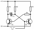
I'm currently exploring monostable multivibrators using 2 transistors. I'd like to know how I should expect the circuit to behave.

The first question I have is:
The "on" time that the circuit will produce, is this a square wave or more like a sawtooth? I've done a circuit where I have an LED connected to the output and I can see the LED fade out. This contradicts the diagram shown on wikipedia (a square wave). Is this happening because something is wrong in my circuit? Or is this expected?

Question 2:
The "on" time is calculated with 0.7*R*C. But does this take into acount the fact that the transistor will be "off" before the capacitor is fully discharged? Because the transistor will probably be "off" when voltage drops below 3v or so on the base. My LED also will stop glowing way before the R*C time has passed if the forward voltage is not met. But if, as per question #1, the output should be a square wave, then this shouldn't be a problem.

Question 3:
I'm still not clear on how the circuit should behave if the the period of the input signal is smaller than the period defined by R*C. In my testing, it seems like the input needs to be low long enough to allow the capacitor to fully recharge. Otherwise, the next trigger is short because it looks like the capacitor was not full. But again, it might be an error in my circuit. Or is this expected?
 

Thread Starter

yesplease

Joined Mar 4, 2020
41
There's a few ways to create a monostable multivibrator but it always seem to come down to the basic diagram as the one on wikipedia. Regardless of the diagram through, the expected behaviour should probably always be the same right? My questions are more oriented towards understanding what is expected from a standard design as opposed to trying to troubleshoot what I've built. So, as a person that has used "monostable multivibrators" in the past, would that person say that what I'm seeing is expected?
 

Attachments

AnalogKid

Joined Aug 1, 2013
11,038
Regardless of the diagram through, the expected behaviour should probably always be the same right?
No.

The schematic is everything, There are several different types of monostables, and several basic circuit variations for each. Without a complete schematic of the exact circuit *you* are testing, everything we do here is guesswork.

ak
 
Last edited:

Thread Starter

yesplease

Joined Mar 4, 2020
41
ok, I understand. So according to the diagram that I've attached in post #3, would you say that my observations are correct? Or should I be expecting different results?
 

MrChips

Joined Oct 2, 2009
30,801
Think of the circuit as a non-inverting amplifier from Q2 to Q1, with capacitive positive feedback from Q1 to Q2.

Let's tackle Question 3 first.

Ques 3(a) What happens if the trigger pulse is shorter than the duration of the monostable?
Ques 3(b) What happens if the trigger pulse is longer than the duration of the mononstable?

A3(b)
Q2 base goes low and stays low. C1 discharges and nothing else happens. Q2 is off and Q1 is on.

A3(a)
Q2 base goes low and C1 is discharged.
If the base of Q2 returns to +V then the collector of Q1 returns to +V . Q2 is on and Q1 is off, i.e. Q1 collector output is the same as the trigger input. There is no delay in the circuit.

Thus something is missing in your circuit for this to function as a monostable multivibrator.

That something is the fact that the input signal is not +V to 0V and back to +V. (Read the caption under the drawing from where this circuit was taken. See below.) The input signal only sinks current and then returns to a high-Z state. One way to fix this circuit is to put a diode (or capacitor) from Q2 base to the input signal.

1644459356670.png

[Basic BJT monostable multivibrator.
The input is high-Z, momentarily goes low, and then back to high-Z. This example is retriggerable.]

Reference: https://en.wikipedia.org/wiki/Monostable_multivibrator
 

Thread Starter

yesplease

Joined Mar 4, 2020
41
Thank you @MrChips .
Then consider the following simulation: https://www.multisim.com/content/wHKUTWL7JLgpifg3hG2UFb/multivibrator/

If the trigger is shorter than the monostable then the monostable ouput falls at the same time than the falling edge of the input.
Does that circuit look correct? I was under the impression that by choosing a value RC that would yield, for example, 2s, then my output would always be 2s, regardless of the period of the input signal.
 

Thread Starter

yesplease

Joined Mar 4, 2020
41
Interesting. It seems I already had an account here and my laptop was already logged in.

They are not 2 user names, but rather 2 different account. This current one being the one I created a few days ago and that other being one that I completely forgot about. I'll continue the discussion with this one.
 

MrChips

Joined Oct 2, 2009
30,801
Interesting. It seems I already had an account here and my laptop was already logged in.

They are not 2 user names, but rather 2 different account. This current one being the one I created a few days ago and that other being one that I completely forgot about. I'll continue the discussion with this one.
Ok. AAC admin @bertus will delete the other account named under pdumais.
You can log out on your laptop and login again with the new name.
 

MrChips

Joined Oct 2, 2009
30,801
I usually don't do simulations.
If you put a Schottky diode in series with the input with the anode on the base of Q2 we can continue the discussion.
 

Thread Starter

yesplease

Joined Mar 4, 2020
41
Thank you for the help. I think I found the answers to my question. For future reference:

Answer1: A properly functioning monostable multivibrator should output a square wave. But it won't be perfect, there will be a small slope on the falling edge. The slope should be very short, and in most case, negligeable in the timeframe calculated by 0.7*R*C

Answer2: Yes, the formula to calculate the time for a monostable multivibrator takes into account any internal components of the system and will define the time of the output. If connecting a LED on to the monostable, then the drop for Vcc to 0 would be very short and the time at which the forwad voltage is not met anymore should, technically, be negligeable (Although this could be critical for some applications)

Answer3: A properly functioning monostable multivibrator should output a signal that is high for the duration defined by R*C. Regardless of the input width.

Another thing to note: Adding a load such as an LED or anything else on the output will change the behaviour of the monostable because it will create a voltage divider. Therefore, the output of the monostable should always be buffered.
 

AnalogKid

Joined Aug 1, 2013
11,038
Answer3: A properly functioning monostable multivibrator should output a signal that is high for the duration defined by R*C. Regardless of the input width.
Not always. Your statement is not correct for either kind of retriggerable monostable, nor for the standard 555 monostable circuit.

That statement is correct only for a "true" monostable, one that has a positive feedback path that is independent of the input. The pseudo-schematic you posted does not have this. Feedback from the Q1 stage and the input trigger signal combine (and collide) at the input (base) to Q2. You can repair the circuit by adding an C-R differentiator to the input. This will trigger the circuit on the leading edge, and the rest of the input pulse will be ignored.

A monostable constructed of two NAND gates (actually, one NAND gate and any type of inverting gate) or two NOR gates (again, one NOR and one inverter) has such a feedback path, and the output pulse is as independent as you describe without a differentiator on the input.

ak
 
Top