Facebook
 Google
 GitHub
 Linkedin
Hello,
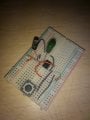
I have an application where I want an output signal to become high for certain duration based on the input trigger, hence decided for designing a monostable multivibrator circuit using 555, I have attached the circuit diagram.
As soon as I turn ON my power supply (5V) the IC is getting hot. I tried running the same circuit in simulation and found that at the ground terminal of the IC I'm getting 5A of current. I'm not sure what is the exact reason for it. Any kind of help would be really appreciated.
Attachments
-
 157.5 KB Views: 61
 -
 17.7 KB Views: 58