 Facebook
 Google
 GitHub
 Linkedin
Hi everyone,
First of all, I'm new on AAC. I'm a student in electronics.
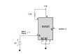
I need to make as final project a high speed flash for a camera. So I thought to take as LED driver the "74121". First I wanted to pick the "555" but this one is too slow... The pulse width needs to be in nanoseconds so I thought this one is perfect. I read if I don't use a capacitor there will be the minimum pulse width (30-35ns), so if I'm using just the minimum R (=1.4k) this can work? (see schematic)
Thanks in advance!
Kind regards
First of all, I'm new on AAC. I'm a student in electronics.
I need to make as final project a high speed flash for a camera. So I thought to take as LED driver the "74121". First I wanted to pick the "555" but this one is too slow... The pulse width needs to be in nanoseconds so I thought this one is perfect. I read if I don't use a capacitor there will be the minimum pulse width (30-35ns), so if I'm using just the minimum R (=1.4k) this can work? (see schematic)
Thanks in advance!
Kind regards
Attachments
-
 10.4 KB Views: 64
") I need 800 images/sec so my flash needs to be lower then 1µs.
I need 800 images/sec so my flash needs to be lower then 1µs.


