Monitor not powering on, ticking noise comming from power board.

Status
Not open for further replies.

Thread Starter

TwentyØnePenguins

Joined Apr 29, 2018
24
#1
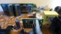
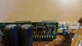
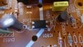
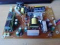
So, a week or so back my monitor died, just out of the blue. So I opened it up, and I see a few bulged capacitors on the power board, and when I plugged it into power, I got a clicking noise. I replaced all caps on the board, but I still get the clicking.

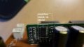
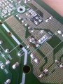
However, I did notice a small capacitor (C806) I forgot to replace(see picture below)
It doesn't have any noticeable bulging or leaking.
(The picture was taken before any caps had been replaced,
that's why some of them may look not very new.)


When I removed that cap and powered the board, I got a more high pitched buzzing noise.
I have no idea if this means anything, but being clear with what I've done may be good so hey xD.
So basically, does anyone know what could be causing this?
Is it that darn capacitor, or is it something else?
If you need any more information or pictures, please ask.

Thank you!

Oh and by the way, hope I got this in the right forum lol

Monitor model number: LSL3230T
 

Attachments

Sounds to me like you may [still] have a short on the board.

A clicking noise? Could that be from a relay being turned on and off? Is that yellow rectangular component near a connector a relay? The idea being that the relay is a safety mechanism to shut off power in an overload situation - to prevent a catastrophic situation like a fire. If that is the case, you have to find the cause of the short...or find a new board.

Why remove "that cap"?
 

Thread Starter

TwentyØnePenguins

Joined Apr 29, 2018
24
Sounds to me like you may [still] have a short on the board.

A clicking noise? Could that be from a relay being turned on and off? Is that yellow rectangular component near a connector a relay? The idea being that the relay is a safety mechanism to shut off power in an overload situation - to prevent a catastrophic situation like a fire. If that is the case, you have to find the cause of the short...or find a new board.

Why remove "that cap"?
(Not really sure why I removed it, was just a little curious what would happened lol)
About the yellow block, according to google that's also some sort of capacitor...
(scc .47k 275v~x2)
However I cant be sure, I'm really not very knowledgeable when it comes to this stuff.
When it comes to shorts, there are several components being soldered together on the underside of the PCB (like shown on picture)

However, since the monitor did work with those in place, I don't really think those have anything to do with it...
 

Attachments

ebp

Joined Feb 8, 2018
2,332
Ticking is often a sign of an overload condition that causes the power supply to turn off, restart, then turn off again.

The small capacitor appears to be part of the main feedback path for regulation. The entire circuit can misoperate if there is a problem with that capacitor if it is in the feedback path. [EDIT:] I looked more closely at the photo and suspect that the capacitor is probably for the power supply for the control circuit for the switcher and probably not directly in the feedback path, but it is still essential to proper operation.

Did you use high-quality low-ESR (equivalent series resistance) capacitors for the replacements? The circuit is a flyback converter and is very demanding of the capacitors - which is why they fail.

Double check all the caps you replaced to be sure they are installed with the correct polarity.

The yellow block is a dual capacitor (not very common) as part of a filter to keep noise from the power supply off the AC line.
 
Last edited:

Thread Starter

TwentyØnePenguins

Joined Apr 29, 2018
24
Ticking is often a sign of an overload condition that causes the power supply to turn off, restart, then turn off again.

The small capacitor appears to be part of the main feedback path for regulation. The entire circuit can misoperate if there is a problem with that capacitor if it is in the feedback path.

Did you use high-quality low-ESR (equivalent series resistance) capacitors for the replacements? The circuit is a flyback converter and is very demanding of the capacitors - which is why they fail.

Double check all the caps you replaced to be sure they are installed with the correct polarity.

The yellow block is a dual capacitor (not very common) as part of a filter to keep noise from the power supply off the AC line.
The replacement capacitors were all Panasonic ones, and I made sure to orient them correctly. All have the same uF rating, however, some are rated 35v instead of 25v like the original ones, but according to what I've read, that should be fine. However, when I ordered those, I completely missed that small one (rated 10 uF 50v). So maybe replacing that would be a good idea, or what do you think?
 

Thread Starter

TwentyØnePenguins

Joined Apr 29, 2018
24
I could pull a 22 uF 50V one from a powerboard I already have, meaning I could test it right now, but I'm not sure if the higher rating would cause any problem in this case...
 
Ticking is often a sign of an overload condition that causes the power supply to turn off, restart, then turn off again.

The small capacitor appears to be part of the main feedback path for regulation. The entire circuit can misoperate if there is a problem with that capacitor if it is in the feedback path. [EDIT:] I looked more closely at the photo and suspect that the capacitor is probably for the power supply for the control circuit for the switcher and probably not directly in the feedback path, but it is still essential to proper operation.

Did you use high-quality low-ESR (equivalent series resistance) capacitors for the replacements? The circuit is a flyback converter and is very demanding of the capacitors - which is why they fail.

Double check all the caps you replaced to be sure they are installed with the correct polarity.

The yellow block is a dual capacitor (not very common) as part of a filter to keep noise from the power supply off the AC line.
I would listen to ebp more than me :) on this. But, while I appreciate your "curiosity", do remember that there are some shock hazards while you "play".
 

ebp

Joined Feb 8, 2018
2,332
Using higher voltage rating for this sort of capacitor usually is actually a benefit because the ripple current rating will typically be somewhat higher and the ESR somewhat lower - but only in comparison with other capacitors in the same series.

It is hard to say if using 22 µF is safe. It very likely is, but without knowing exactly what it is doing I can't be sure.
Determining if it is the filter cap for the power for the control circuit by tracing circuitry shouldn't be too daunting. Typically the negative side will connect directly to a pin of the transformer and a bunch of other places (the common for the whole input side of the switcher). The positive side will have a diode, possibly with a resistor in series, to another transformer pin. There will be a fairly high-value resistor, often a 1 or 2 watt type, from the positive side of the cap to the positive side of the main filter capacitors after the bridge rectifier from the AC power input. Be careful of residual charge on the main filter caps.
If it can be verified that the circuit is like this, increasing the value to 22 µF should be OK.

In a circuit as I described, the small capacitor is first charged through the resistor from the input supply. When the voltage on the cap gets sufficiently high, the control circuit will start and the voltage on the cap will be maintained from the transformer. If something is wrong in the main power path, the voltage may not be maintained from the transformer and the current through start-up resistor is too low to keep the circuit running. The control circuit will shut down when the cap voltage falls to some threshold. This reduces the current required by the control circuit, the cap can charge again from the input supply and the the circuit tries to start again. There is a slight risk that higher capacitance can keep the circuit going longer than what is desirable under fault conditions, but the higher capacitance also slows the retry rate.
 

Dodgydave

Joined Jun 22, 2012
11,395
" Ticking" is a classic symptom of a switchmode psu in over current mode, there is a problem on one of the outputs being pulled down. Current sense is usually monitored by a sense resistor in the Source leg of the power mosfet.

If you can't get the service manual, can you see what is the smps chip number?

The capacitor you have noted looks like it's on the feedback path of the opto-coupler.
 
Last edited:

Thread Starter

TwentyØnePenguins

Joined Apr 29, 2018
24
Using higher voltage rating for this sort of capacitor usually is actually a benefit because the ripple current rating will typically be somewhat higher and the ESR somewhat lower - but only in comparison with other capacitors in the same series.

It is hard to say if using 22 µF is safe. It very likely is, but without knowing exactly what it is doing I can't be sure.
Determining if it is the filter cap for the power for the control circuit by tracing circuitry shouldn't be too daunting. Typically the negative side will connect directly to a pin of the transformer and a bunch of other places (the common for the whole input side of the switcher). The positive side will have a diode, possibly with a resistor in series, to another transformer pin. There will be a fairly high-value resistor, often a 1 or 2 watt type, from the positive side of the cap to the positive side of the main filter capacitors after the bridge rectifier from the AC power input. Be careful of residual charge on the main filter caps.
If it can be verified that the circuit is like this, increasing the value to 22 µF should be OK.

In a circuit as I described, the small capacitor is first charged through the resistor from the input supply. When the voltage on the cap gets sufficiently high, the control circuit will start and the voltage on the cap will be maintained from the transformer. If something is wrong in the main power path, the voltage may not be maintained from the transformer and the current through start-up resistor is too low to keep the circuit running. The control circuit will shut down when the cap voltage falls to some threshold. This reduces the current required by the control circuit, the cap can charge again from the input supply and the the circuit tries to start again. There is a slight risk that higher capacitance can keep the circuit going longer than what is desirable under fault conditions, but the higher capacitance also slows the retry rate.
Having a schematic for this would make this so much easier lol
Anyhow, if I were to replace that one, and it would fail, is there a way to know what would break, the capacitor or something else on the board.
 

Thread Starter

TwentyØnePenguins

Joined Apr 29, 2018
24
" Ticking" is a classic symtom of a switchmode psu in over current mode, there is a problem on one of the outputs being pulled down. Current sense is usually monitored by a sense resistor in the Source leg of the power mosfet.

If you can't get the service manual, can you see what is the smps chip number?

The capacitor you have noted looks like it's on the feedback path of the opto-coupler.
I'm quite the noob at this, how do I find the correct chip? xD
(There is one chip on the board, and then there are multiple chips on the two "daughter boards".)
 

Dodgydave

Joined Jun 22, 2012
11,395
Yes disconnect/unsolder the output side, theres probably two outputs, you need to get a Multimeter before you start playing with switchmode psus,.
 
Status
Not open for further replies.
Top