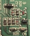
Bingo! It's a Tl431 zener, the two resistors 4701( 4.7k) 1201 (1.2k) set the voltage, you can make the 1.2k smaller or increase the 4.7k to get the ratios, i would go with the 1.2k and drop it to 1.06k by putting a 9601 (9.6k) in parallel , this will give you 13.6V output...
Vout now = (1+ 4k7 /1k2) x 2.5v= 12.3V.
Vout new = (1+ 4k7 /1k06) x 2.5v = 13.6V
Rapping it round the join with a heavy screwdriver handle sometimes parts it without too much damage. Practice on a few scrap ones first.
If its too fiddly to hand trace the circuit - it probably won't be easy to modify.
Voltage sensing is usually a simple 2 resistor divider feeding a comparator (which might be in a TL431). You can calculate Vref from the original divider ratio and re calculate the resistors for the new voltage. The empirical method is adding high value resistors in parallel with the bottom divider resistor till the output comes up to what you want. If you use a pre set pot - put it in place of the bottom divider resistor in case the wiper comes loose.
Rapping it round the join with a heavy screwdriver handle sometimes parts it without too much damage. Practice on a few scrap ones first.
If its too fiddly to hand trace the circuit - it probably won't be easy to modify.
Voltage sensing is usually a simple 2 resistor divider feeding a comparator (which might be in a TL431). You can calculate Vref from the original divider ratio and re calculate the resistors for the new voltage. The empirical method is adding high value resistors in parallel with the bottom divider resistor till the output comes up to what you want. If you use a pre set pot - put it in place of the bottom divider resistor in case the wiper comes loose.
Thanks Dave. Since there's a spot right next to it I'll peruse my stock of old boards and find one and lay it along side on the extra pads. May have to double up something to get a good resistance.
I've decided to go with a fixed resistance of 6.6K Ω and a variable (10 turn) 5K Pot. That will give me an adjustable range of 13.3 volts to 14.1 volts. If I go with a lower fixed resistance, 4.7K Ω I can get a range of 13.48 to 14.8. Not a big fan of the possibility of pushing that supply that high, nor am I in favor of possibly way over charging a car battery. Going with a 10K (10 turn) Pot will allow me to drop the voltage down to 13 volts but I lose some of the adjustment sensitivity. Small moves make bigger jumps with the 10K. I also looked at 20 and 50K but don't care for the lack of sensitivity (too coarse) adjustment.
Thanks all for your help. And thanks Dave for noticing what I would have overlooked for days - the 431 device being the primary reference for the output. I MIGHT have figured it out - one day, but probably by then I'd have lost interest in the project. All that's left is to build into the box the fixed and variable resistance and make the pot accessible through the top.
Ok, if you want to put a 5k multiturn pot in you can put a 1k pot also in series for fine adjustment if needed, to be on the safe side make sure you uprate the output capacitors to 25V, they're probably 16V rated now.
That type of supply probably wouldn't be harmed - but some of the secondary side components would bleed away charge from the battery if power went down.
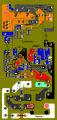
For those who may be curious of the boards construction: I've taken a picture and cartooned it so I could color code some of the traces. I've also included as much information as possible regarding components, but because so much is under potting it's impossible to read without taking things off. Somewhere in text, first page probably, are some descriptions of some of the components.
There is a circuit diagram on the datasheet, post#23, the extra primary winding( blue black) is for self power once it's kicked up on pin1, the main primary winding is Red Blue fed by the mosfet.
This is the last part of the puzzle. Do you have a data sheet that shows pinout? On my circuit board it looks like pin 1 is a gate of some sort. I'd like to know more about that part.
Yes its on the datasheet i gave you in post#23. As a matter of overvoltage protection, remove the zener Zd1,across the output or the zero ohm link on it's anode.
That's the data sheet for the NE1109F. I've seen a data sheet for the MOSFET, the FTA06N60D, but there is only the one page and it contains a lot of Asian characters (Chinese - Japanese - I don't know). No pin out other than some information RichardO posted in post #14. Unless I'm missing something. I do that too often.

 Facebook
 Google
 GitHub
 Linkedin