Mod for a latching circuit ON/OFF

Thread Starter

EmaCO2

Joined Apr 24, 2018
11
Hello guys,

I'm new in the forum and this is my first post. Happiness!

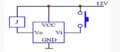
So, I've found a cheap latching flip/flop circuit on eBay (link below).
It works fine but I would like to add a feature: I want the circuit to be triggered by holding the button for 3 or 5 seconds, and to be turned back OFF holding the button again for 3 or 5.

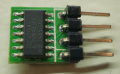
On the board there is a HEF4013B.

Is it feasible? Let me know.
Thanks!
 

Attachments

crutschow

Joined Mar 14, 2008
38,503
What if you hold it for more than 5 seconds?
Or do you just want a minimum 3 second hold time?

Need the schematic to the complete circuit.

Do you have a link to the ebay source? You said "link below" but there was no link.
 

Thread Starter

EmaCO2

Joined Apr 24, 2018
11
Hello Crutschow and thanks for the quick reply:
The idea is that the circuit gets triggered after 3 seconds and it stay ON until the next impulse (again, of 3 seconds).
Unfortunately I didn't find the schematic, but maybe the data sheet is enough for sorting out something. Apparently, the Vi (please see the pinout picture) goes straight to the pin 3 of the HEF4013, which corresponds to the clock input.

The eBay link is HERE

Speak soon and thanks a lot!
 

crutschow

Joined Mar 14, 2008
38,503
Without know what the circuit on the board is, we can only guess.
Can you post a clear picture of the top and bottom of the board.
 

AnalogKid

Joined Aug 1, 2013
12,126
Still not clear enough. What are the three lines of writing on the chip?

Separate from that, a small circuit based on one CD4093 or CD40106 can take a button press that is continuous for x time and generate a short output pulse at the end of x time. It is a retriggerable monostable followed by a standard monostable. If you let go of the button at 2.9 seconds, there is no output pulse; the input timer restarts at 0 seconds when the button is pressed again

ak
 

crutschow

Joined Mar 14, 2008
38,503
Can't tell enough about that circuit to suggest a modification.
Think you'll have to built a new add-on circuit to add the trigger delay.:(
 

Thread Starter

EmaCO2

Joined Apr 24, 2018
11
Can't tell enough about that circuit to suggest a modification.
Think you'll have to built a new add-on circuit to add the trigger delay.:(
Thanks anyway.
Anyway, I'm happy to make a new circuit from scratch. I tried to search another thread where a similar topic has been discussed, but no success.
 

Thread Starter

EmaCO2

Joined Apr 24, 2018
11
Still not clear enough. What are the three lines of writing on the chip?

Separate from that, a small circuit based on one CD4093 or CD40106 can take a button press that is continuous for x time and generate a short output pulse at the end of x time. It is a retriggerable monostable followed by a standard monostable. If you let go of the button at 2.9 seconds, there is no output pulse; the input timer restarts at 0 seconds when the button is pressed again

ak
The three writing on the chip are:
HEF4013BT
NXP CHW54204
TnD15392

I'll research about the CD4093 or CD40106 and see what I'lI find.

Thank you!
 

crutschow

Joined Mar 14, 2008
38,503
Here's a circuit using a CD4013 FF with a delay added from the push-button output to the clock input using a CD4093 Schmitt trigger circuit.
The Schmitt trigger is needed to generate the required fast rise-time clock to reliably trigger the CD4013.

The LTspice simulation shows the circuit ignoring the first PB pulse of 2.9s but triggering for the following two 3.1s pulses.
You can change the value of R5 (or use a pot for that resistor) to adjust the delay time.

upload_2018-4-25_9-23-35.png
 
Top