Pulse Latching Circuit

Thread Starter

moonlystar1111

Joined Feb 1, 2024
106
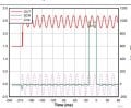
I'm working on a project where I have a pulse that stays high for a certain duration, as shown in the figure below. What I need is a circuit or IC that can maintain this high pulse continuously until I press a reset button (or apply another control signal like OV or 5V).

In short, the pulse should stay high indefinitely until the reset condition is triggered.

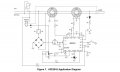
Can anyone suggest a circuit design or IC that can latch the pulse in this way? Any guidance or recommendations would be highly appreciated!

Looking forward to your thoughts and suggestions!
 

Attachments

Last edited:

sghioto

Joined Dec 31, 2017
8,633
In short, the pulse should stay high indefinitely until the reset condition is triggered.
What will this High output pulse be connected to?
Should this High output pulse be at the same voltage level as the trigger pulse?
What supply voltages are available?
One suggestion:
1737088356948.png
 
Last edited:

boostbuck

Joined Oct 5, 2017
1,034
The sample circuit you show should work as you want it to if you connect the SCR and its load across a dc supply - the SCR will then remain conducting until the load current is interrupted.
 

MisterBill2

Joined Jan 23, 2018
27,186
That original circuit looks like a GFI (ground fault interrupter) and those devices do a solid hard latch that requires a mechanical reset.
SO I am suggesting that the TS needs to provide a lot more detail about the application before any more suggestions, because a GFI system is potentially a "LIFE CRITICAL SYSTEM"!!!
 

Thread Starter

moonlystar1111

Joined Feb 1, 2024
106
What will this High output pulse be connected to?
Should this High output pulse be at the same voltage level as the trigger pulse?
What supply voltages are available?
One suggestion:
View attachment 340537
The high output pulse will be connected to gate of scr.
Yes this high pulse should be at same voltage level.
Supply voltages are 5vdc, 20 vdc and 120vac.
Thanks for your suggestion with 555 timer. I think jk flip flop will also be used to reduce the circuit.
 

MisterBill2

Joined Jan 23, 2018
27,186
It still does not make much sense to me, WHAT are you trying to accomplish?? And the circuit still looks like a ground fault interrupter. SO just what is the goal?????
 
Top